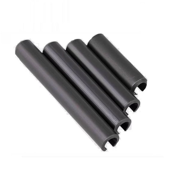
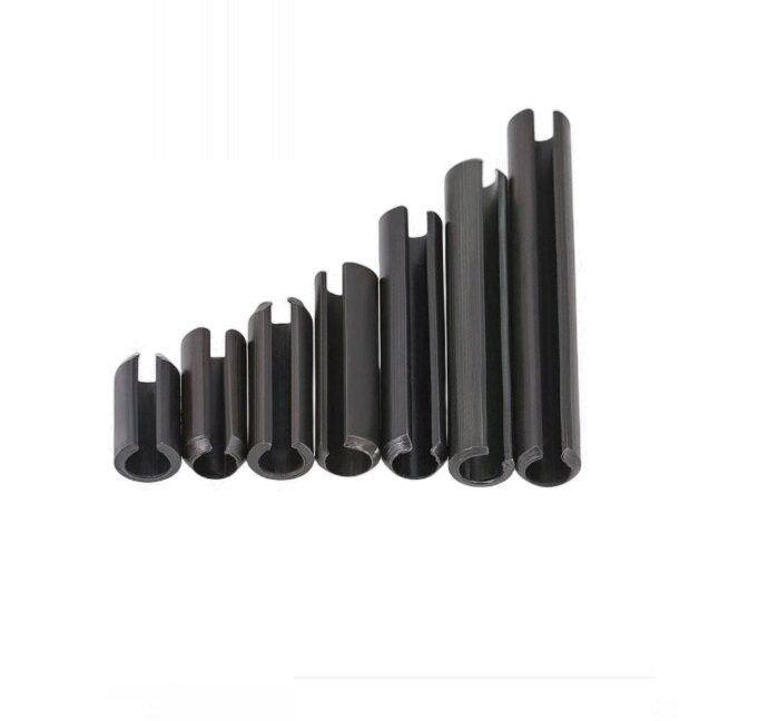
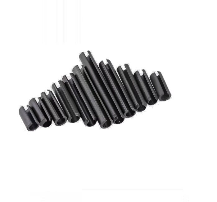
Inch slotted spring pins in 65Mn spring steel for mechanical assembly and replacement. Select nominal diameter and length from 104 sizes. Sold in packs of 5 or 10.
Inch Slotted Spring Pins / Split Roll Pins
These hollow cylindrical pins have one longitudinal slot. They compress during installation into a suitable mating hole. Use them for pinning and retaining components in mechanical assemblies after confirming the required fit, loading and installation conditions.
Nominal diameter range: 1/16–1/2 inch (1.5875–12.7 mm).
Material: 65Mn spring steel, as identified by the supplier.
Structure: slotted spring pin, also called a split roll pin. Match the slot construction when replacing an existing pin.
Diameter 5/16, 3/8, 7/16 and 1/2 inch: packs of 5. Other diameters: packs of 10.
Displayed price is per selected pack. Quantity 1 means one pack, not one individual pin.
Specifications
Property
Information
Material
65Mn spring steel (supplier identification)
Construction
Hollow slotted cylindrical spring pin
Sizing
Nominal diameter × length; inch sizes with metric equivalents
Standard reference
Supplier references ASME B18.8.2; no independent conformity certificate is supplied
Hardness reference
Supplier states HRC 42–46; no batch test report is supplied
Manufacturer / source brand
Meiluo (supplier brand)
Package contents
Selected spring pins only; 5 or 10 pieces according to size
Order status
Pre-order; confirm dispatch timing before purchase
How to Select the Correct Size
Identify the nominal pin diameter and the required pin length. Nominal diameter is the size designation, not the outside diameter of an uncompressed pin.
Check the actual mating hole and the installation requirements. The supplier hole ranges below are reference guidance, not guaranteed fit tolerances.
Select the complete size and check the pack quantity. For example, 3/8 × 3/4 inch is nominal diameter 9.525 mm × length 19.05 mm and contains 5 pins.
Use a suitable installation method for your assembly. Confirm engineering suitability before using a pin in a load-bearing or safety-critical connection.
1 inch = 25.4 mm. Metric values in the model table are unit conversions of nominal inch sizes. The special 1/8 inch × 21.5 mm model uses a metric length. The product reference illustrations are not to scale and do not specify wall thickness, free-state outside diameter, chamfer dimensions or production tolerances.
Diameter Series and Supplier Hole Guidance
The following diameter series are selection guidance only. They are not separate products or purchasable options. Supplier reference hole ranges are based on the supplied source information and should be checked against your actual assembly.
Nominal diameter (in)
Nominal diameter (mm)
Supplier hole guidance (mm)
1/16
1.5875
1.575–1.65
3/32
2.38125
2.39–2.46
1/8
3.175
3.175–3.27
5/32
3.96875
3.96–4.06
3/16
4.7625
4.75–4.87
7/32
5.55625
5.56–5.69
1/4
6.35
6.35–6.5
5/16
7.9375
7.92–8.07
3/8
9.525
9.53–9.7
7/16
11.1125
11.1–11.3
1/2
12.7
12.7–12.95
Available Sizes and Pack Quantities
All dimensions below are nominal. Prices are in USD per pack.
Size
Nominal diameter (mm)
Length (mm)
Pieces per pack
Price / pack (USD)
SKU
1/16 x 1/4 in
1.5875
6.35
10
17
DG-SP-6070085965309
1/16 x 5/16 in
1.5875
7.9375
10
17
DG-SP-6070085965310
1/16 x 3/8 in
1.5875
9.525
10
17
DG-SP-6070085965284
1/16 x 1/2 in
1.5875
12.7
10
19
DG-SP-6070085965311
3/32 x 1/4 in
2.38125
6.35
10
4.8
DG-SP-6070085965312
3/32 x 5/16 in
2.38125
7.9375
10
4.8
DG-SP-6070085965313
3/32 x 3/8 in
2.38125
9.525
10
4.8
DG-SP-6070085965314
3/32 x 7/16 in
2.38125
11.1125
10
5.6
DG-SP-6070085965315
3/32 x 1/2 in
2.38125
12.7
10
6
DG-SP-6070085965316
3/32 x 5/8 in
2.38125
15.875
10
6.4
DG-SP-6070085965317
3/32 x 3/4 in
2.38125
19.05
10
7.2
DG-SP-6070085965318
3/32 x 1 in
2.38125
25.4
10
8
DG-SP-6070085965319
3/32 x 1-1/2 in
2.38125
38.1
10
9.6
DG-SP-6070085965320
1/8 x 3/8 in
3.175
9.525
10
5.6
DG-SP-6070085965285
1/8 x 7/16 in
3.175
11.1125
10
5.8
DG-SP-6070085965321
1/8 x 1/2 in
3.175
12.7
10
6
DG-SP-6070085965286
1/8 x 9/16 in
3.175
14.2875
10
6.2
DG-SP-6070085965322
1/8 x 5/8 in
3.175
15.875
10
6.4
DG-SP-6070085965287
1/8 x 3/4 in
3.175
19.05
10
6.5
DG-SP-6070085965288
1/8 x 21.5mm
3.175
21.5
10
7
DG-SP-6070085965370
1/8 x 7/8 in
3.175
22.225
10
7.2
DG-SP-6070085965289
1/8 x 1 in
3.175
25.4
10
7.2
DG-SP-6070085965290
1/8 x 1-1/4 in
3.175
31.75
10
8
DG-SP-6070085965291
1/8 x 1-1/2 in
3.175
38.1
10
8.8
DG-SP-6070085965292
1/8 x 2 in
3.175
50.8
10
14
DG-SP-6070085965356
1/8 x 2-1/2 in
3.175
63.5
10
11
DG-SP-6070085965323
5/32 x 1/2 in
3.96875
12.7
10
8
DG-SP-6070085965324
5/32 x 5/8 in
3.96875
15.875
10
8
DG-SP-6070085965357
5/32 x 3/4 in
3.96875
19.05
10
9.6
DG-SP-6070085965325
5/32 x 7/8 in
3.96875
22.225
10
9
DG-SP-6070085965326
5/32 x 1 in
3.96875
25.4
10
9
DG-SP-6070085965327
5/32 x 1-1/4 in
3.96875
31.75
10
10.2
DG-SP-6070085965358
5/32 x 1-1/2 in
3.96875
38.1
10
11.8
DG-SP-6070085965359
5/32 x 1-3/4 in
3.96875
44.45
10
13.4
DG-SP-6070085965360
5/32 x 2 in
3.96875
50.8
10
15
DG-SP-6070085965328
3/16 x 1/4 in
4.7625
6.35
10
6.4
DG-SP-6070085965329
3/16 x 3/8 in
4.7625
9.525
10
4.8
DG-SP-6070085965293
3/16 x 7/16 in
4.7625
11.1125
10
4.8
DG-SP-6070085965330
3/16 x 1/2 in
4.7625
12.7
10
5
DG-SP-6070085965294
3/16 x 5/8 in
4.7625
15.875
10
6.4
DG-SP-6070085965295
3/16 x 3/4 in
4.7625
19.05
10
6.5
DG-SP-6070085965296
3/16 x 7/8 in
4.7625
22.225
10
7.2
DG-SP-6070085965331
3/16 x 1 in
4.7625
25.4
10
7.5
DG-SP-6070085965297
3/16 x 1-1/8 in
4.7625
28.575
10
8
DG-SP-6070085965361
3/16 x 1-1/4 in
4.7625
31.75
10
8.8
DG-SP-6070085965298
3/16 x 1-1/2 in
4.7625
38.1
10
9.6
DG-SP-6070085965332
3/16 x 1-3/4 in
4.7625
44.45
10
11
DG-SP-6070085965333
3/16 x 2 in
4.7625
50.8
10
12
DG-SP-6070085965334
3/16 x 2-1/4 in
4.7625
57.15
10
15
DG-SP-6070085965335
3/16 x 2-1/2 in
4.7625
63.5
10
16.6
DG-SP-6070085965336
3/16 x 2-3/4 in
4.7625
69.85
10
19
DG-SP-6070085965337
7/32 x 3/8 in
5.55625
9.525
10
9
DG-SP-6134441408999
7/32 x 7/16 in
5.55625
11.1125
10
9
DG-SP-6134441409000
7/32 x 1/2 in
5.55625
12.7
10
9
DG-SP-6070085965348
7/32 x 5/8 in
5.55625
15.875
10
10
DG-SP-6249693830902
7/32 x 3/4 in
5.55625
19.05
10
11
DG-SP-6070085965349
7/32 x 7/8 in
5.55625
22.225
10
12
DG-SP-6249693830903
7/32 x 1 in
5.55625
25.4
10
13
DG-SP-6070085965350
7/32 x 1-1/4 in
5.55625
31.75
10
15
DG-SP-6249693830904
7/32 x 1-1/2 in
5.55625
38.1
10
17
DG-SP-6070085965351
1/4 x 1/2 in
6.35
12.7
10
5.6
DG-SP-6070085965299
1/4 x 5/8 in
6.35
15.875
10
6.4
DG-SP-6070085965300
1/4 x 3/4 in
6.35
19.05
10
7.2
DG-SP-6070085965301
1/4 x 7/8 in
6.35
22.225
10
7.5
DG-SP-6070085965302
1/4 x 1 in
6.35
25.4
10
8
DG-SP-6070085965303
1/4 x 1-1/8 in
6.35
28.575
10
8.8
DG-SP-6070085965362
1/4 x 1-1/4 in
6.35
31.75
10
9.6
DG-SP-6070085965304
1/4 x 1-1/2 in
6.35
38.1
10
9
DG-SP-6070085965305
1/4 x 1-5/8 in
6.35
41.275
10
11
DG-SP-6070085965363
1/4 x 1-3/4 in
6.35
44.45
10
11.8
DG-SP-6070085965338
1/4 x 2 in
6.35
50.8
10
12.6
DG-SP-6070085965306
1/4 x 2-1/4 in
6.35
57.15
10
13.4
DG-SP-6070085965307
1/4 x 2-1/2 in
6.35
63.5
10
15
DG-SP-6070085965339
1/4 x 2-3/4 in
6.35
69.85
10
19
DG-SP-6070085965364
1/4 x 3 in
6.35
76.2
10
23
DG-SP-6070085965340
1/4 x 3-1/2 in
6.35
88.9
10
27
DG-SP-6070085965341
5/16 x 3/4 in
7.9375
19.05
5
4.8
DG-SP-6070085965342
5/16 x 1 in
7.9375
25.4
5
6.4
DG-SP-6070085965343
5/16 x 1-1/4 in
7.9375
31.75
5
6.8
DG-SP-6070085965344
5/16 x 1-1/2 in
7.9375
38.1
5
7.2
DG-SP-6070085965308
5/16 x 1-3/4 in
7.9375
44.45
5
8
DG-SP-6070085965345
5/16 x 2 in
7.9375
50.8
5
8.8
DG-SP-6070085965346
5/16 x 2-1/2 in
7.9375
63.5
5
9
DG-SP-6070085965347
5/16 x 3 in
7.9375
76.2
5
11
DG-SP-6070085965365
3/8 x 3/4 in
9.525
19.05
5
7.2
DG-SP-5836027146640
3/8 x 1 in
9.525
25.4
5
8
DG-SP-5836027146641
3/8 x 1-1/4 in
9.525
31.75
5
9.6
DG-SP-5836027146642
3/8 x 1-1/2 in
9.525
38.1
5
9.4
DG-SP-5836027146643
3/8 x 1-3/4 in
9.525
44.45
5
10.2
DG-SP-5836027146644
3/8 x 2 in
9.525
50.8
5
11.8
DG-SP-5836027146645
3/8 x 2-1/4 in
9.525
57.15
5
13
DG-SP-5836027146647
3/8 x 2-1/2 in
9.525
63.5
5
14.2
DG-SP-5836027146648
3/8 x 3 in
9.525
76.2
5
15
DG-SP-5836027146649
3/8 x 4 in
9.525
101.6
5
24
DG-SP-6257363678813
7/16 x 1 in
11.1125
25.4
5
10.5
DG-SP-5836027146652
7/16 x 1-1/4 in
11.1125
31.75
5
12.5
DG-SP-5836027146653
1/2 x 1 in
12.7
25.4
5
14
DG-SP-5836027146655
1/2 x 1-1/2 in
12.7
38.1
5
19
DG-SP-5836027146656
1/2 x 1-3/4 in
12.7
44.45
5
21
DG-SP-5836027146657
1/2 x 2 in
12.7
50.8
5
24
DG-SP-5836027146658
1/2 x 2-1/2 in
12.7
63.5
5
27
DG-SP-5836027146659
1/2 x 2-3/4 in
12.7
69.85
5
29
DG-SP-5836027146660
1/2 x 3 in
12.7
76.2
5
31
DG-SP-5922418224708
1/2 x 4 in
12.7
101.6
5
39
DG-SP-5836027146661
Series Reference Photographs
Series reference photograph. Use the selected model size to confirm the ordered dimensions and pack quantity.Series reference photograph. Use the selected model size to confirm the ordered dimensions and pack quantity.Series reference photograph. Use the selected model size to confirm the ordered dimensions and pack quantity.
Frequently Asked Questions
Is this a slotted or coiled spring pin?
This product has a single longitudinal slot. Check that this construction matches the pin required for your assembly.
Does quantity 1 mean one pin?
No. Quantity 1 means one pack. The selected size contains either 5 or 10 pins, as stated in the selector and model table.
Can I use a metric hole for an inch pin?
Check the actual hole size, required fit and assembly conditions. The metric equivalents describe nominal pin sizes. They are not interchangeable-fit guarantees.
Are installation tools included?
No. Each pack contains only the selected pins.
How should the pins be stored?
Store dry and protect the pins from moisture. No corrosion-resistance rating is supplied.
When will my order ship?
Confirm dispatch timing before purchase. Shipping options and after-sales terms follow the store policies linked below.
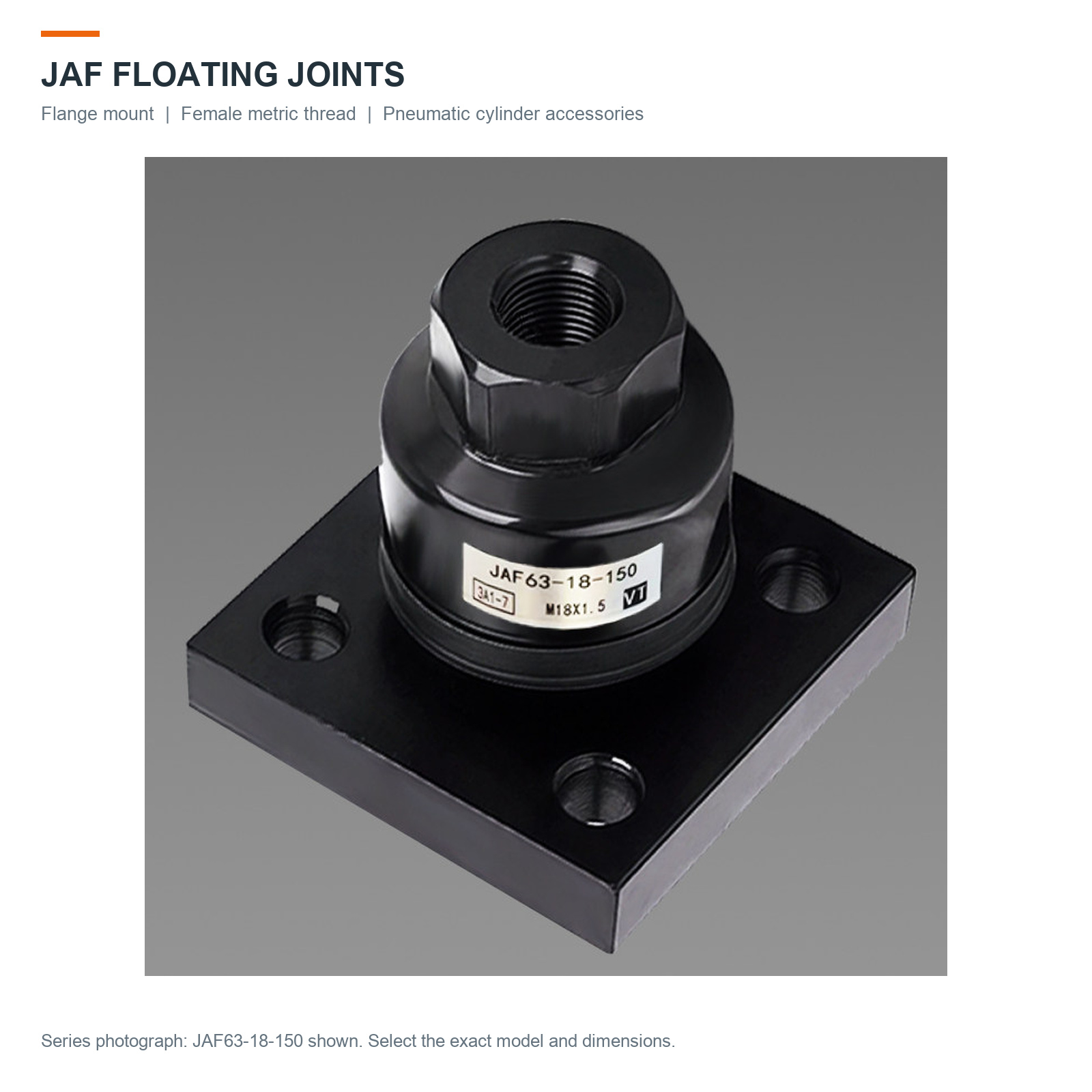
Connect a compatible pneumatic cylinder rod to a guided driven assembly with a female-thread floating joint and mounting flange. The floating connection accommodates limited alignment variation between the rod and the driven part. Choose the complete thread specification and flange dimensions for your assembly.
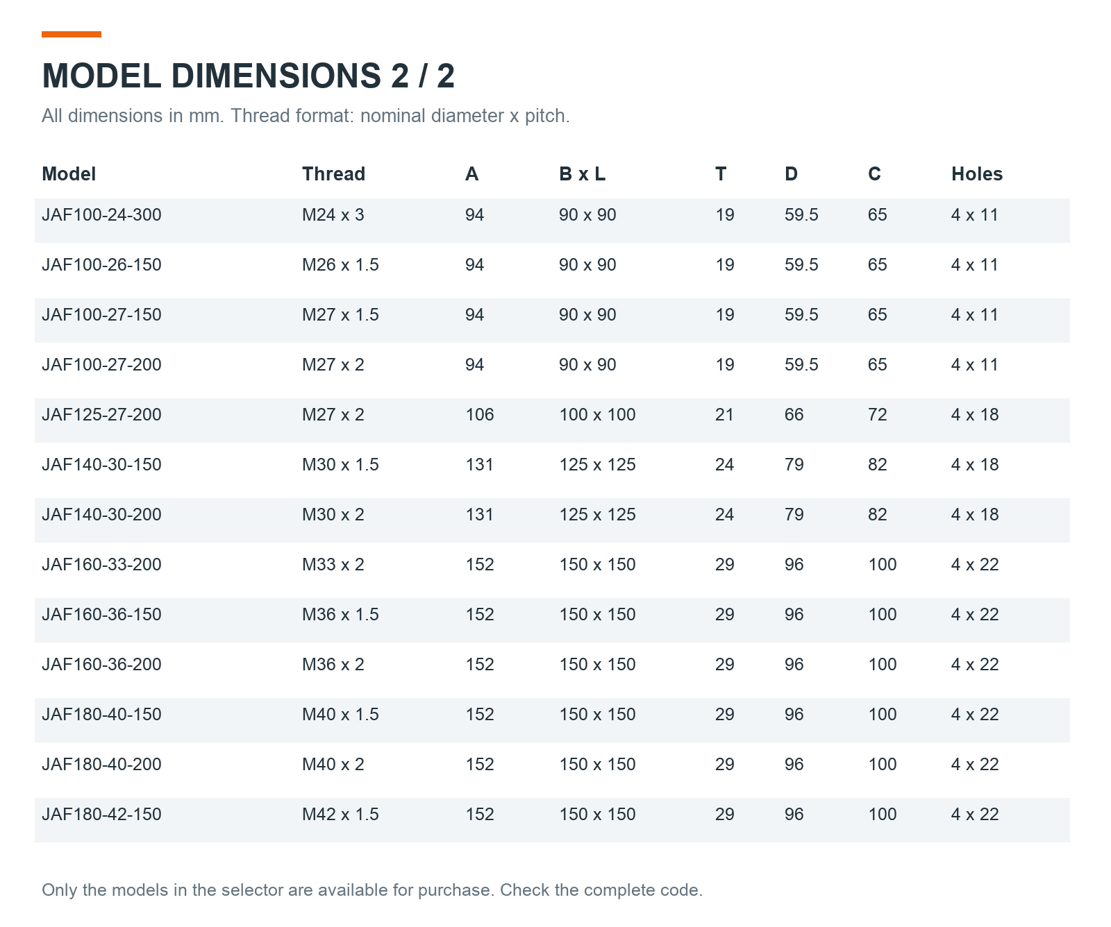
27 model options, with female metric threads from M10 to M42.
Two-hole rectangular flanges on the listed JAF25, JAF30, JAF32 and JAF40 models; four-hole square flanges on JAF50 and larger listed models.
Black-finished body with a dust-cover design. The supplier identifies the housing material as cast iron.
Price is for one selected floating joint with its flange. The cylinder and driven assembly are not included.
Select Your Model
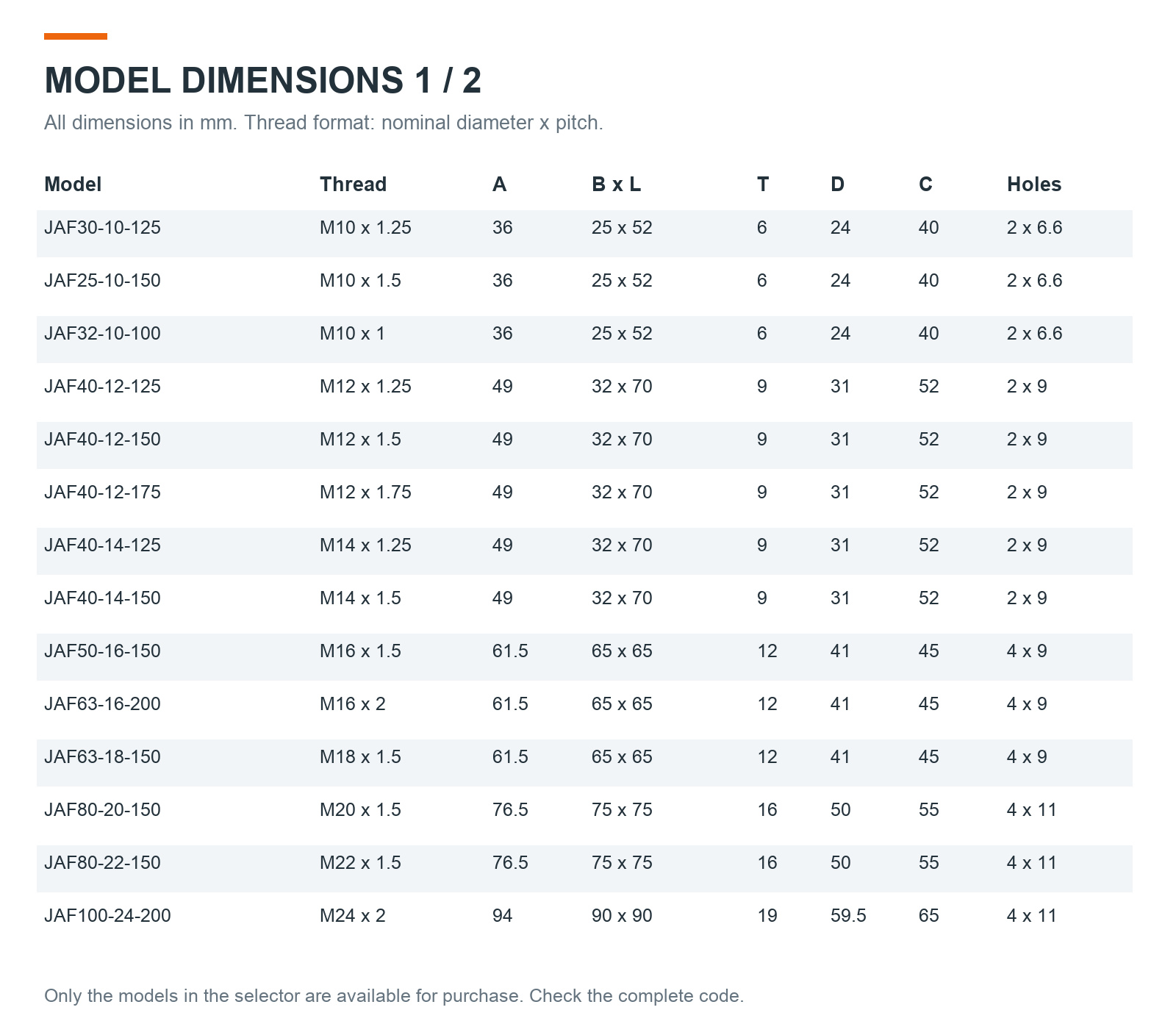
For example, JAF63-18-150 uses an M18 x 1.5 female thread and a 65 x 65 mm four-hole flange. The final three digits specify thread pitch in hundredths of a millimetre: 100 = 1.0 mm, 125 = 1.25 mm, 150 = 1.5 mm, 175 = 1.75 mm, 200 = 2.0 mm and 300 = 3.0 mm.
Match the cylinder rod's thread diameter and pitch, then check overall height, flange size, mounting-hole pattern and available clearance. The series number alone does not establish cylinder compatibility. Confirm maximum axial load, permitted misalignment and operating conditions for your application before ordering. These limits are not specified by the listed price.
Specifications
Material
Cast iron housing, supplier specification
Connection
Female metric thread
Thread range
M10–M42, model-dependent pitch
Mounting
Two-hole or four-hole flange, by model
Included quantity
1 floating joint with mounting flange
Model selection
Full JAF code, thread pitch and flange dimensions
Product Photos & Technical Details
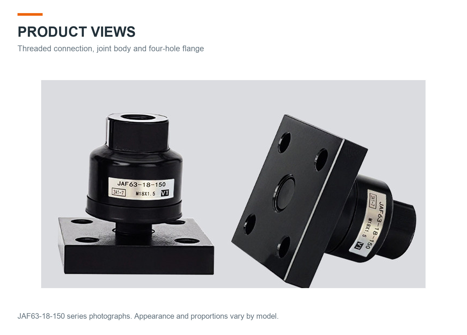
Click images to enlarge. Series photographs show a JAF63-18-150 example. Each model option has its own English dimension sheet, using the supplied model illustration and a flange schematic.
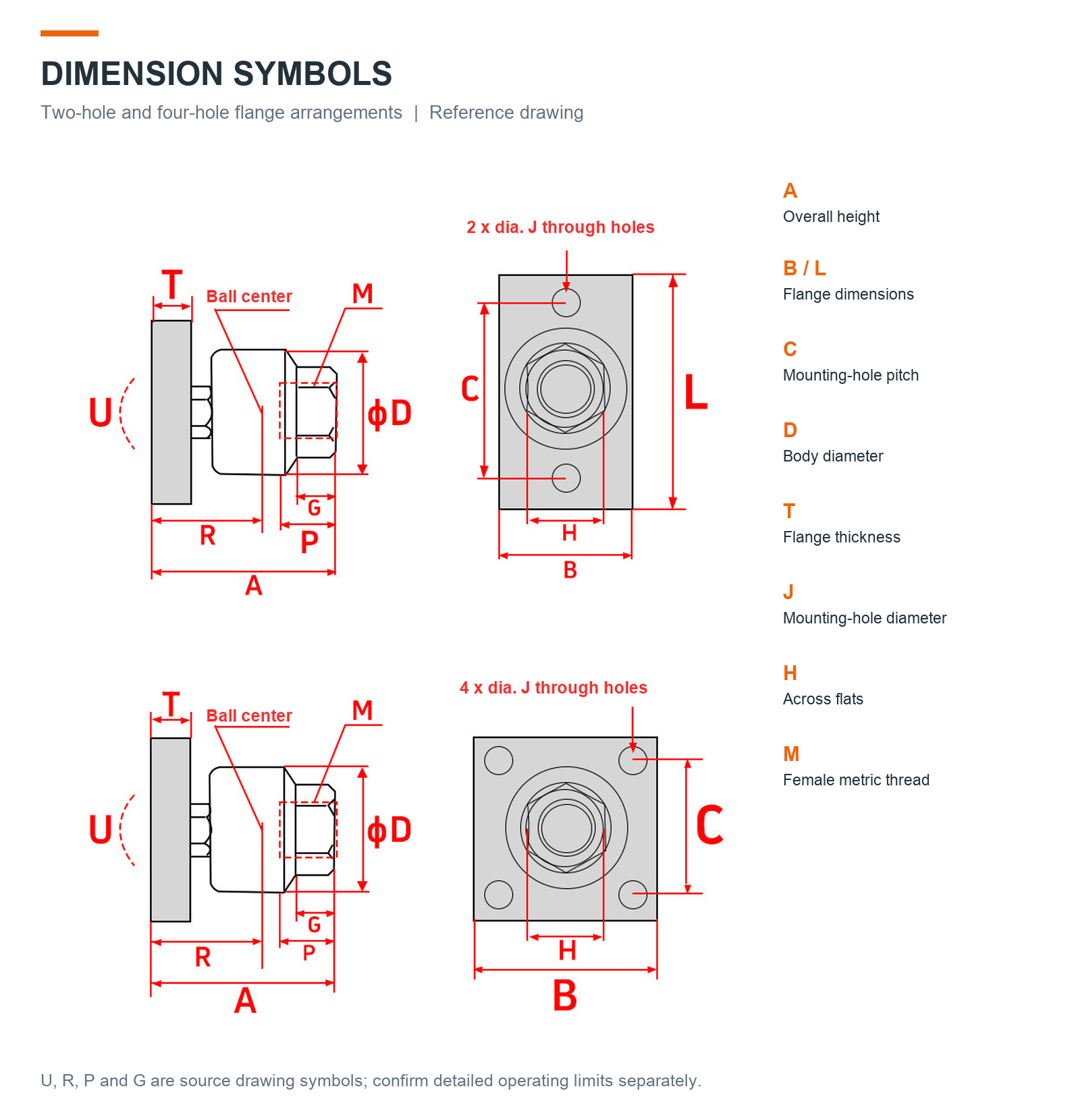
JAF63-18-150 series photograph. The supplied model determines the dimensions.Actual series product views, including the flange and female thread.Reference drawing symbols for two-hole and four-hole flange arrangements.Listed model dimensions, page 1 of 2. Dimensions in mm.Listed model dimensions, page 2 of 2. Dimensions in mm.Model selection, included item and ordering information.
Available Models
A: overall height; B x L: flange dimensions; T: flange thickness; D: body diameter; C: hole-center spacing; H: width across flats. All linear dimensions are in mm. Model drawings are nominal reference illustrations and are not to scale.
Shoulder bushings provide a mating bore for locating pins in jigs, fixtures and positioning assemblies. The shoulder provides an axial seating surface. Choose the complete series, bore and total length to suit your installation.
SUJ2 bearing steel, as specified in the supplied product data.
YEY01: no surface treatment. YEY02: hard chrome plated.
Nominal bore diameter D: 5–25 mm, depending on model.
Price is for one selected bushing. A locating pin and installation tools are not included.
How to Select
D is the locating bore diameter, L is the total length including the shoulder, and D1 is the body outside diameter. The nominal shoulder outside diameter is D1 + 2 mm; its nominal axial length is 3 mm. V is the lead-in length shown in the supplied dimensional reference. All dimensions are in millimetres.
Select the finish and complete model code together. Confirm the mating pin and mounting bore before ordering. Nominal model schematics are not photographs or certified production drawings. Groove and edge details in these schematics are illustrative; they do not define machining dimensions. For fit tolerances, hardness verification or detailed installation requirements, contact us before purchase.
Series Reference Photograph
Series reference photograph. Select your model using the corresponding dimension schematic.
MDD Threaded Cantilever Pins with Retaining-Ring Groove
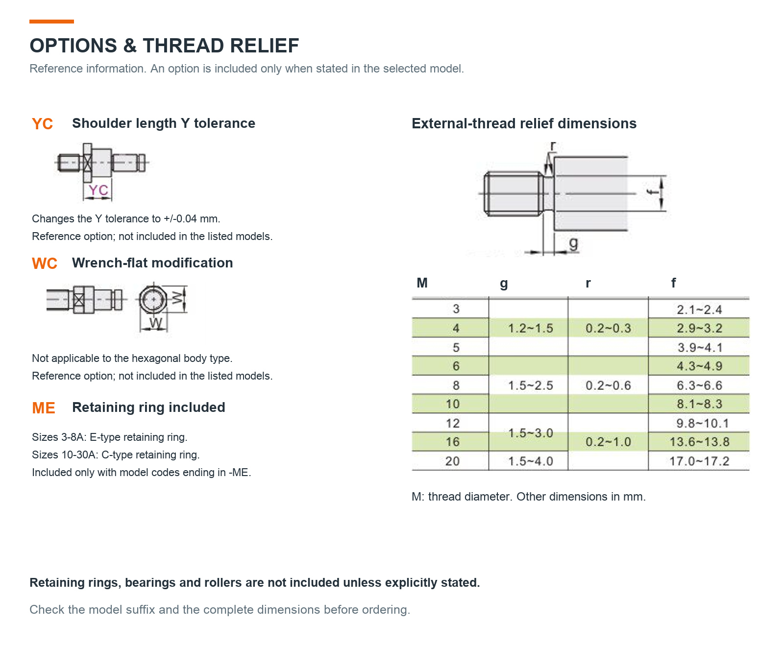
Threaded cantilever pins provide a projecting shaft for compatible rollers, bearings and fixture assemblies. The external mounting thread secures the pin to a tapped support, while the shoulder provides a seating surface. A groove near the shaft end accepts a retaining ring.
22 model options with nominal shaft diameters D from 3 to 15 mm.
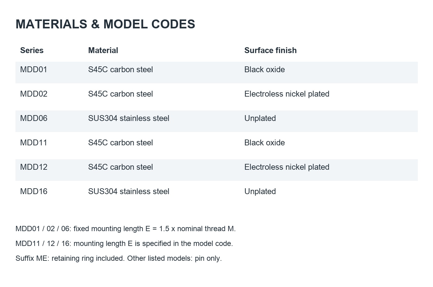
S45C carbon steel with black oxide or electroless nickel finish, or unplated SUS304 stainless steel, depending on the model.
Choose the complete model code to match the diameter, shoulder length, shaft length and mounting length.
Price is for one selected pin. Bearings, rollers and mounting assemblies are not included.
A retaining ring is included only with models ending in -ME. Other models are supplied without a retaining ring.
Read the Model Code
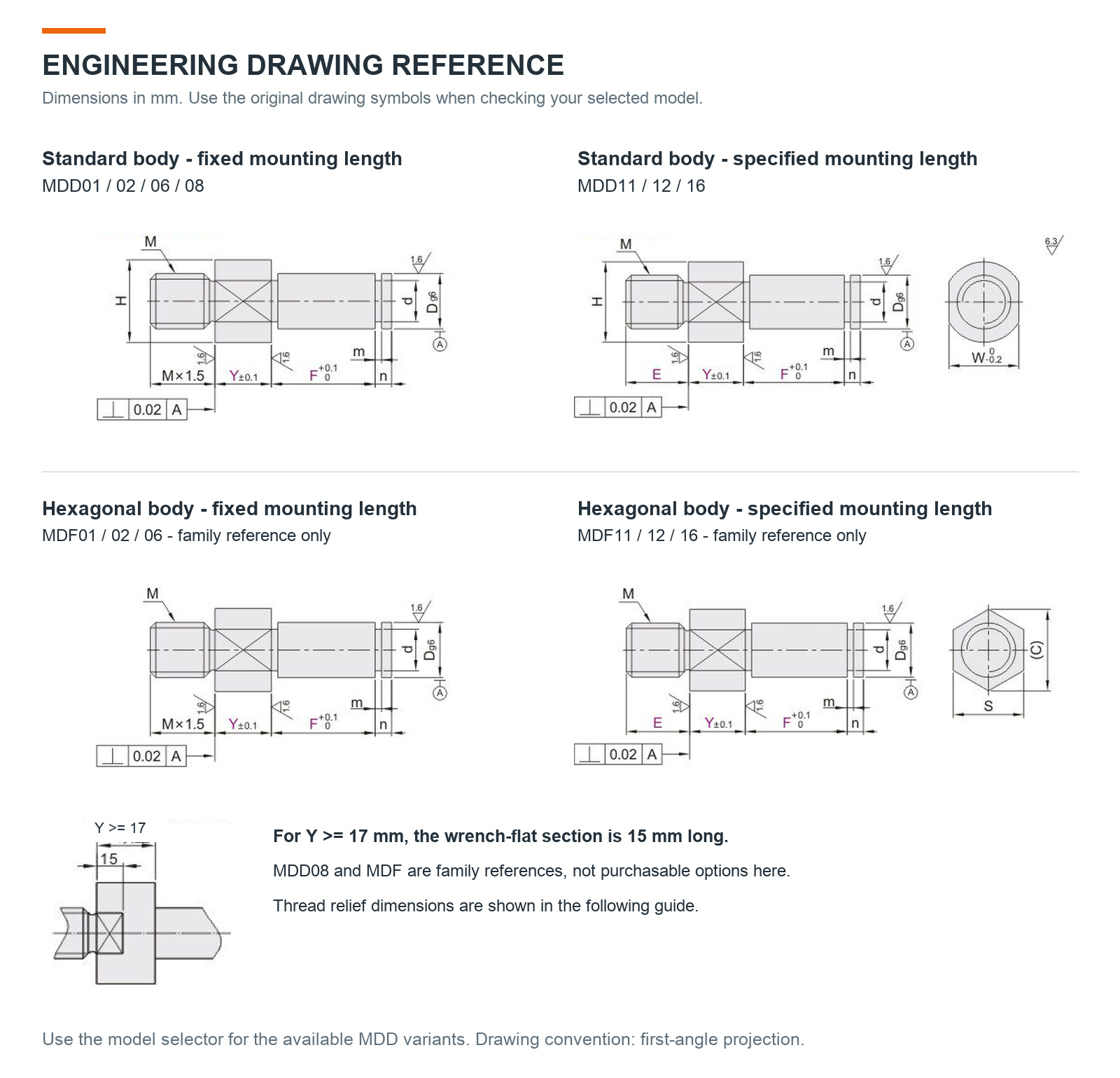
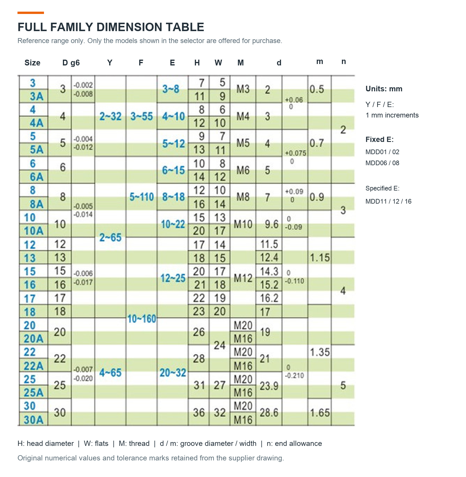
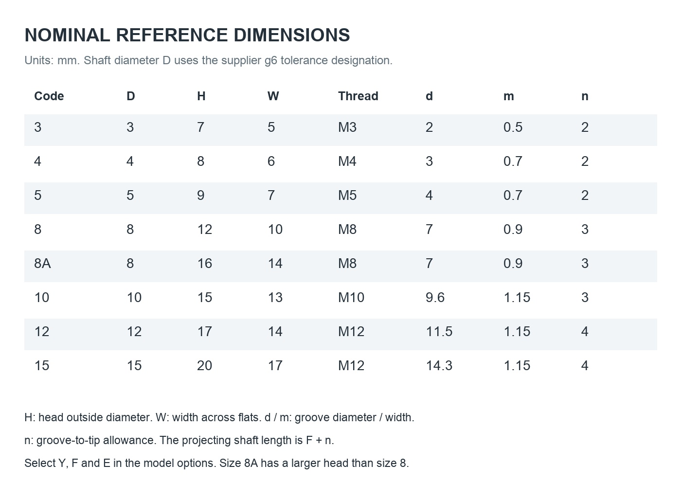
Example: MDD12-8A-Y4-F16-E12 identifies series MDD12, size code 8A, shoulder length Y of 4 mm, length F of 16 mm and mounting length E of 12 mm. Size 8A has the same nominal shaft diameter as size 8, with a larger head and width across flats.
D = shaft diameter; Y = shoulder length; F = shaft length from the shoulder to the start of the retaining-ring groove; E = mounting length; M = metric mounting thread; H = head outside diameter; W = width across flats. The projecting shaft length is F + n, where n is the groove-to-tip allowance. All linear dimensions are in millimetres.
For MDD01, MDD02 and MDD06, mounting length E is fixed at 1.5 times the nominal thread size M. For MDD11, MDD12 and MDD16, E is specified in the model code. When Y is 17 mm or greater, the supplier drawing specifies a 15 mm long wrench-flat section.
Specifications
Material
S45C carbon steel or SUS304 stainless steel, by model
Mounting
External metric thread with shoulder
Shaft diameter D
3–15 mm; supplier drawing designation g6
Surface finish
Black oxide, electroless nickel plated or unplated, by series
Included quantity
1 pin; retaining ring only for -ME options
Check the full model, mating thread, bearing bore and available mounting space before ordering. Select the material and finish appropriate for your application. Contact us if you need load ratings, fit verification or a custom dimension; these are not specified by the listed price alone.
Product Photos & Technical Details
Click any image to enlarge it. Photographs show the product series. Select a complete model code for the exact dimensions and finish.
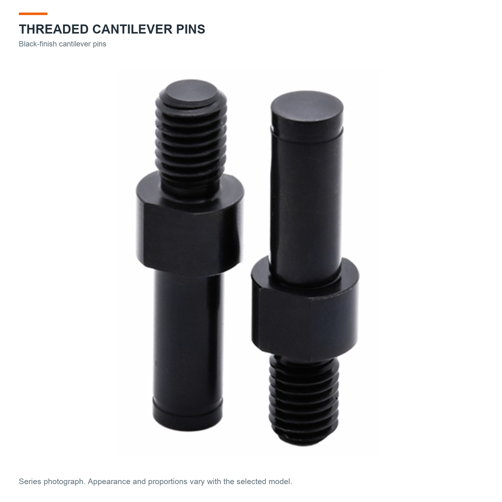
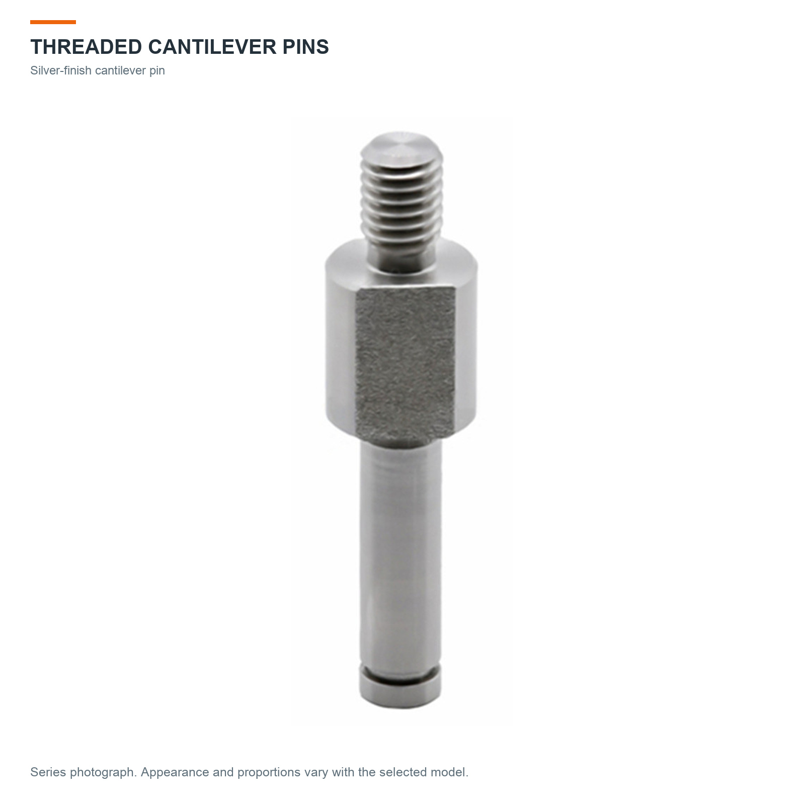
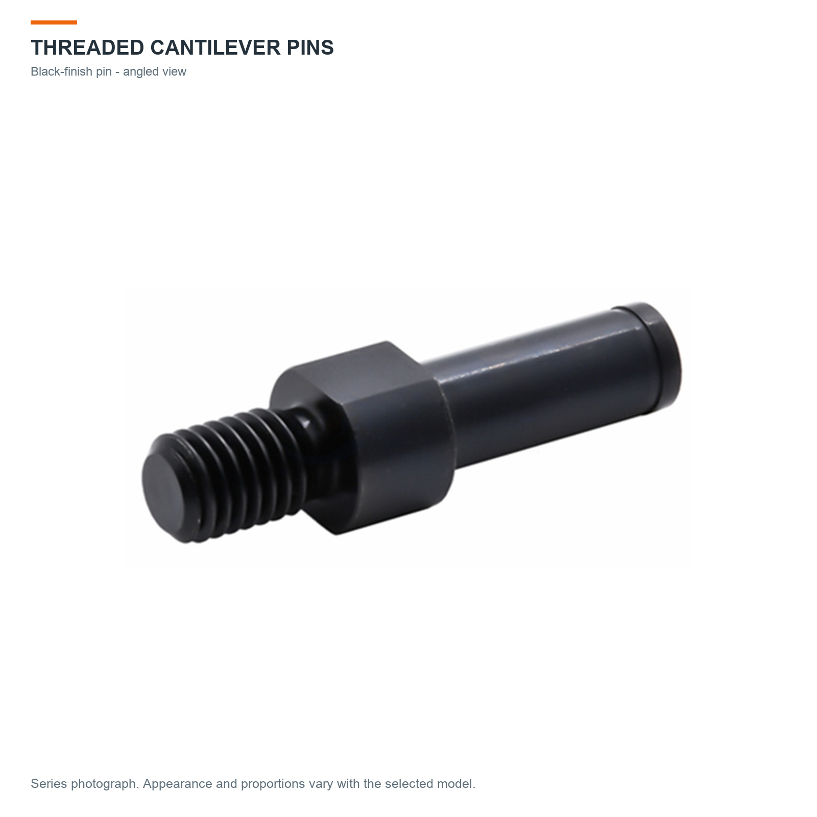
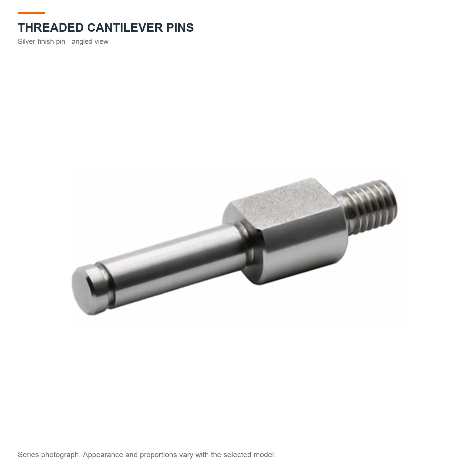
Black finish — MDD series photograph; proportions vary by model.Silver finish — MDD series photograph; proportions vary by model.Black angled view — MDD series photograph; proportions vary by model.Silver angled view — MDD series photograph; proportions vary by model.
Materials & Finishes
Materials, surface finishes and model-series guide.
Engineering Drawings
Original engineering geometry with English explanations. MDF and MDD08 are family references only.
Full Family Dimensions
Full family dimension table. Only model options in the selector are offered for purchase.
Listed Size Reference
Nominal reference dimensions for the listed size codes.
Options & Thread Relief
Retaining-ring options and external-thread relief dimensions.
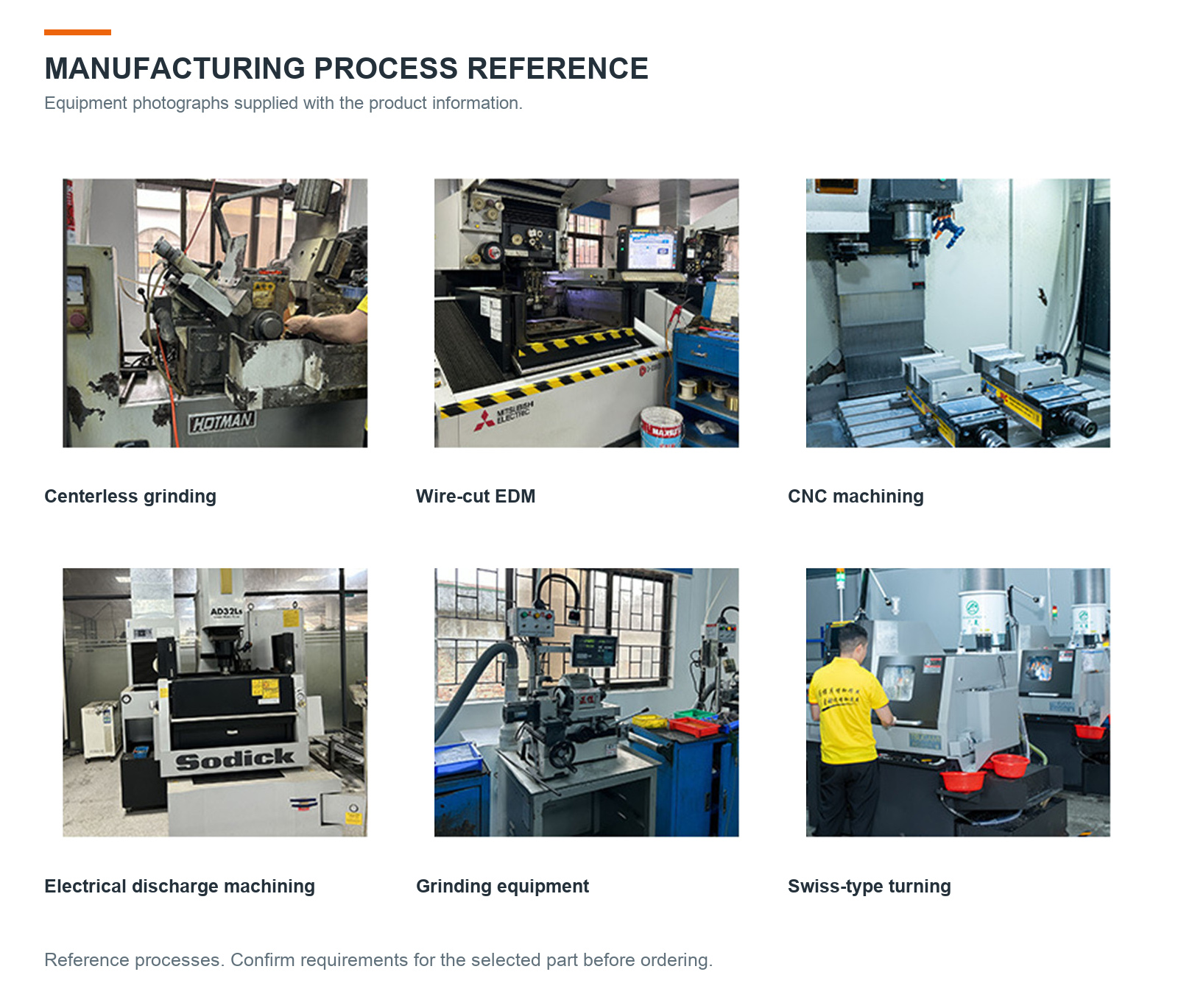
Manufacturing Reference
Manufacturing equipment photographs supplied with the product information.
Ordering Information
Model selection, included items, product images, shipping and contact information.
Available Models
The model selector shows a dedicated English dimension schematic for each option. Schematics are not photographs or production drawings.
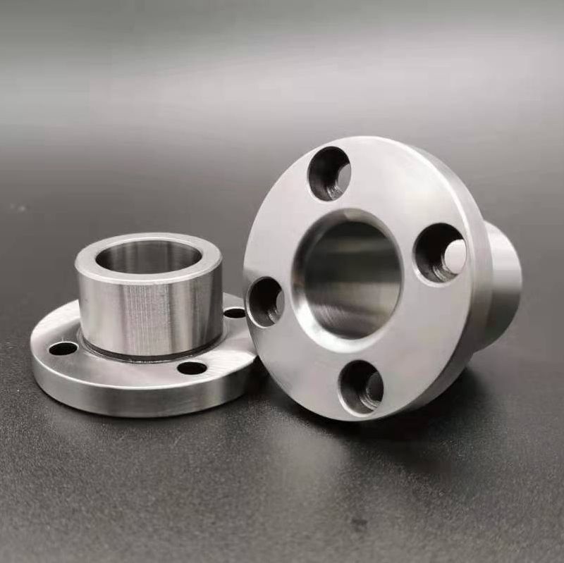
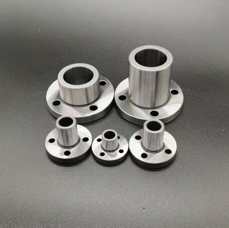
JBY bushings provide a mating bore for a locating pin in jigs, fixtures and positioning assemblies. A round flange with four counterbored mounting holes allows the bushing to be fastened to a compatible fixture plate.
Round flange, four mounting holes and a cylindrical locating bore.
Hardened steel construction.
36 selectable models, with nominal bore sizes from 8 to 25 mm.
Choose the model code and length together. For example, JBY8-12 has an 8 mm bore and length L of 12 mm.
Price is for one selected bushing. A locating pin is not included.
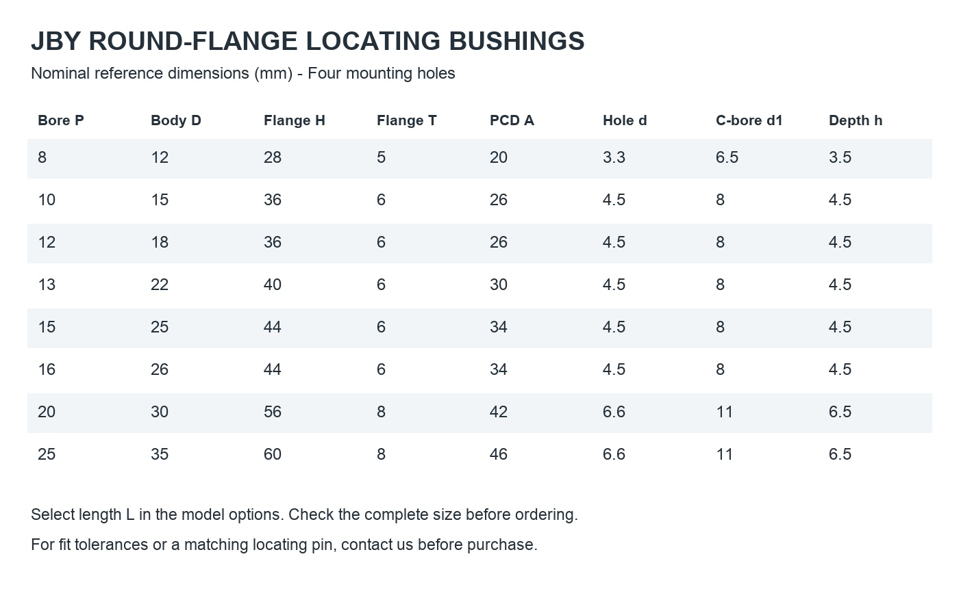
Model and Dimension Selection
P is the bore diameter; D is the body outside diameter; H is the flange outside diameter; T is the flange thickness; A is the mounting-hole pitch circle. Length L is measured from the underside of the flange to the end of the body, as shown in the dimension schematic. All dimensions are in millimetres.
Check the bore, mounting-hole pattern and installation space before ordering. Contact us if your assembly requires a particular fit tolerance, hardness certificate or matching locating pin. The model images are nominal dimension schematics, not photographs or production drawings. Product photographs show examples from the series.
Specifications
Material
Hardened steel
Mounting
Round flange, four counterbored holes
Bore
8–25 mm, depending on model
JBY round-flange locating bushings - product reference photographJBY nominal reference dimensions in millimetresJBY round-flange bushings - series reference photograph
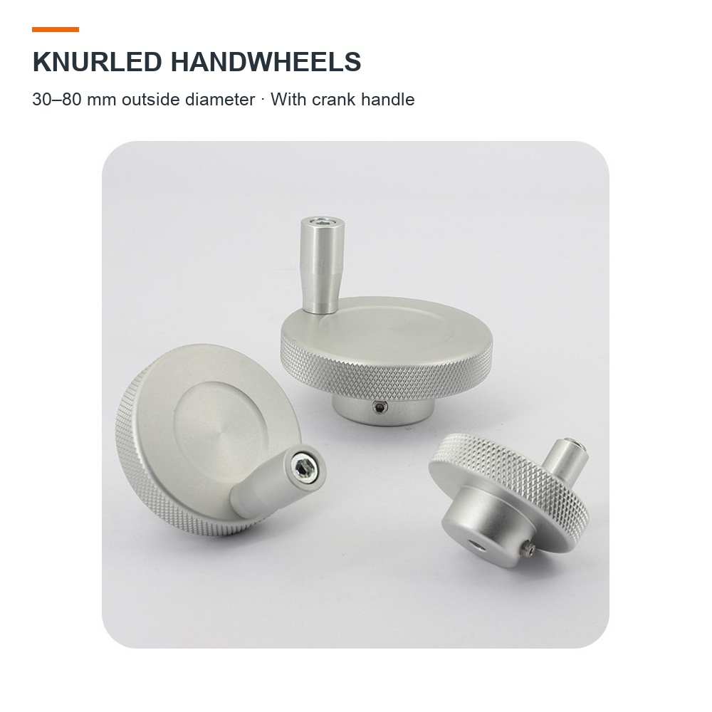
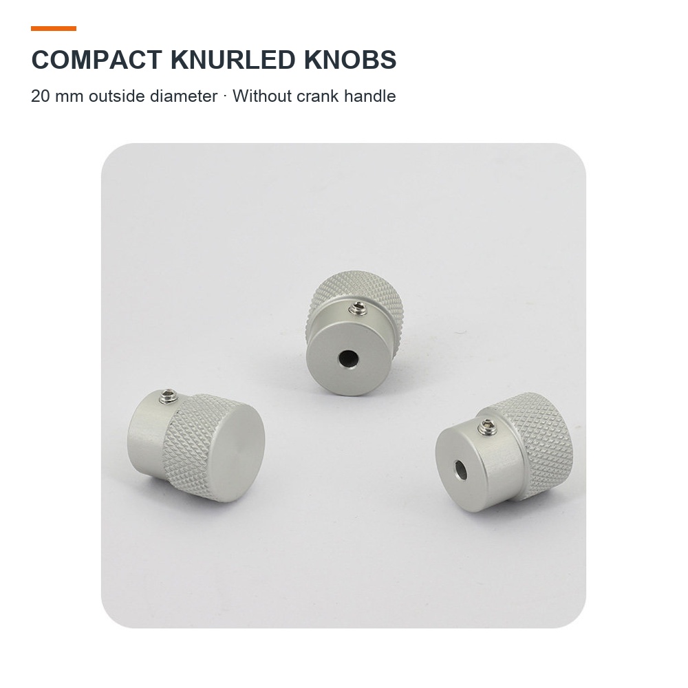
Choose a compact knob or a crank-handle handwheel for manual adjustment on compatible machine tools, lead screws, slide tables and other mechanisms. The diamond-knurled rim provides a textured grip, while the hub uses a radial set screw to secure the selected bore to a shaft.
Aluminum alloy body with a silver-colored finish.
20 mm outside diameter: compact knob, without a crank handle.
30, 40, 50, 60 and 80 mm outside diameters: supplied with a crank handle.
51 size options. Select the outside diameter and bore diameter together.
Price is for one selected handwheel or knob. Hex key is not included.
Specifications
Material
Aluminum alloy
Outside diameter
20, 30, 40, 50, 60 or 80 mm
Bore diameter
4–25 mm, depending on outside diameter
Mounting
Round bore with radial set screw
Choose the Right Model
Match the bore to your shaft and check the outside diameter, bore depth and space around the handle. Dimensions are in millimetres. The model selector displays the corresponding dimension image and unit price. For a required fit tolerance or application load, contact us before ordering.
Handwheels with crank handles — 30 to 80 mm outside diameterCompact knobs without crank handles — 20 mm outside diameter
Available Models
OD = outside diameter. Bore depth is the depth shown in the model dimension image.
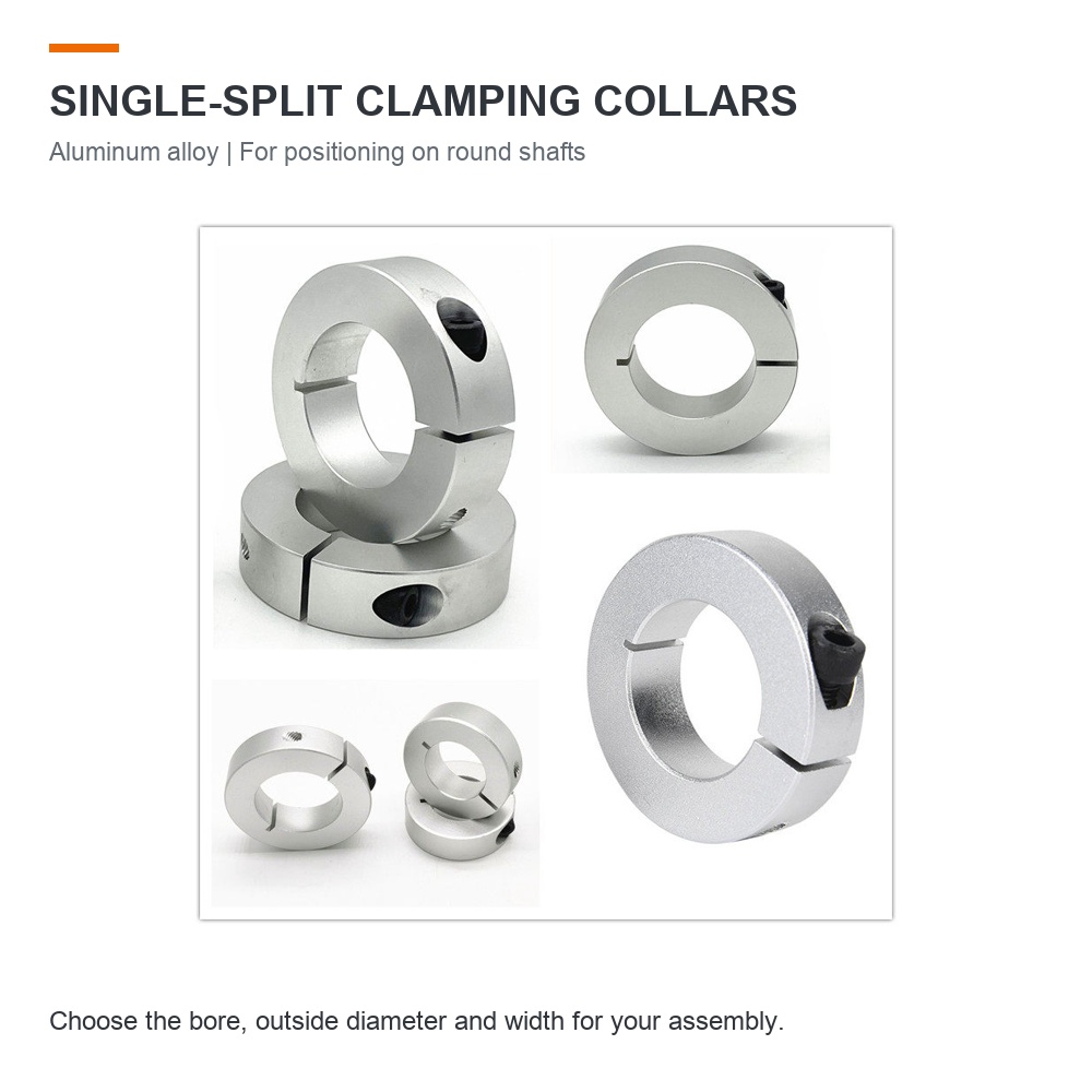
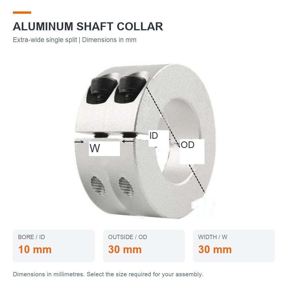
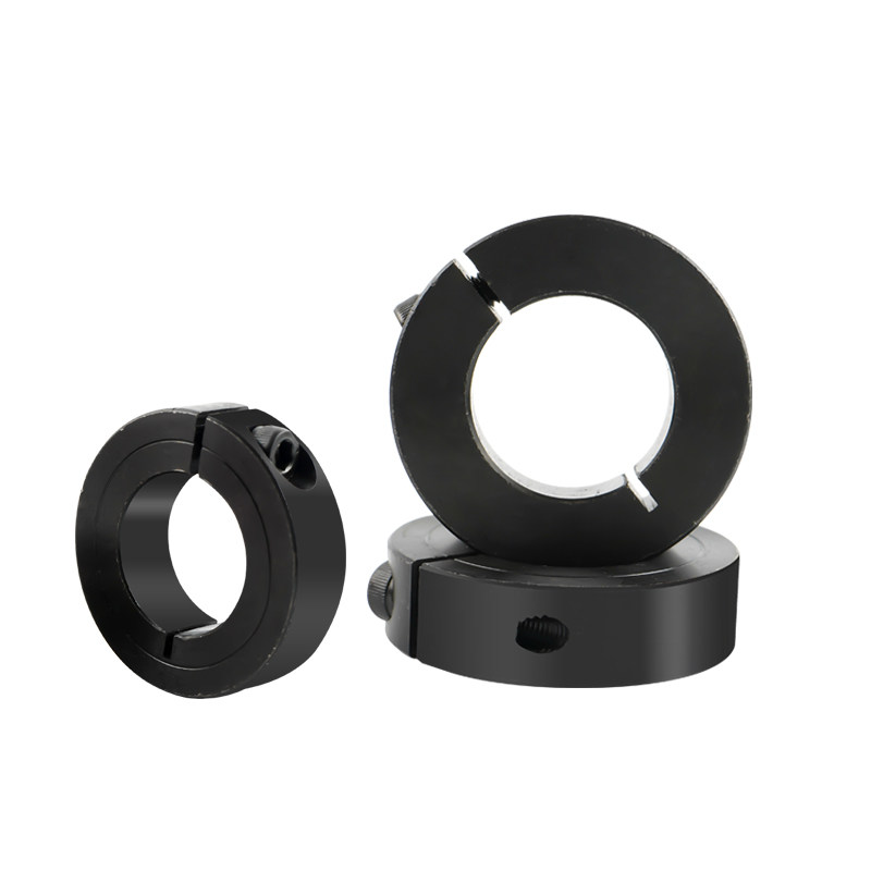
Position components on round shafts with a single-split aluminum collar. Select the bore diameter, outside diameter and width for your assembly. Extra-wide models feature two clamping screws as shown in their images.
Material: aluminum alloy.
Single-split design with standard-width and extra-wide options.
72 dimensional options, with bore sizes from 4 to 100 mm.
Dimensions: ID (bore) × OD (outside diameter) × W (width), in millimetres.
Unit price is per collar. Check the selected model before ordering.
Selecting Your Collar
Check the shaft diameter, available outside clearance and collar width. Specific alloy grade, dimensional tolerances and load capacity are not confirmed for every model in the supplied data. Contact us when these specifications are critical to your application.
The ID 10 × OD 30 × W 12 mm option uses a labelled dimension schematic because its source photograph is unavailable.
Single-split aluminum shaft collarsAxial positioning and travel-stop applicationsExtra-wide two-screw collar: ID 10 × OD 30 × W 30 mm
Model Dimensions
Use the model selector above to view the corresponding image and price.
Design
Bore ID (mm)
Outside OD (mm)
Width W (mm)
Single split
4
16
8
Single split
5
20
8
Single split
6
20
8
Single split
6
20
10
Single split
7
20
8
Single split
8
20
8
Single split
8
25
8
Single split
8
25
10
Single split
9
25
8
Single split
10
30
8
Single split
10
30
10
Single split
10
30
12
Extra-wide single split
10
30
30
Single split
11
30
10
Single split
12
30
8
Single split
12
30
10
Single split
12
30
12
Extra-wide single split
12
30
30
Single split
13
30
10
Single split
14
30
10
Single split
14
30
12
Single split
15
35
10
Single split
15
35
12
Single split
16
35
10
Single split
16
35
12
Single split
16
35
15
Single split
17
35
10
Single split
17
35
12
Single split
17
35
15
Single split
18
40
12
Single split
19
40
12
Single split
20
40
12
Single split
20
35
8
Single split
20
40
10
Single split
20
40
15
Single split
20
45
12
Single split
20
45
15
Single split
21
40
12
Single split
22
40
12
Single split
22
45
12
Single split
24
45
12
Single split
25.4
45
15
Single split
25
45
12
Single split
25
45
15
Single split
25
50
15
Single split
28
50
15
Single split
26
45
12
Single split
27
45
12
Single split
28
45
12
Single split
28
48
15
Single split
30
55
15
Single split
30
50
10
Single split
30
50
12
Single split
30
50
15
Single split
32
60
15
Single split
35
60
15
Single split
38
60
15
Single split
38
70
18
Single split
40
70
18
Single split
40
60
12
Single split
40
60
15
Single split
40
70
15
Single split
42
70
18
Single split
45
80
22
Single split
50
70
15
Single split
50
80
22
Single split
50
85
22
Single split
55
85
22
Single split
60
95
22
Single split
70
115
22
Single split
80
130
30
Single split
100
150
36
Need Help Selecting a Size?
Send us your shaft dimensions, quantity and application requirements.
Illustrations and supplier reference sheets below cover different collar series. Match the design and dimensions to the selected model. Two-piece examples, a single-split drawing and SCS single-split tables are identified separately.
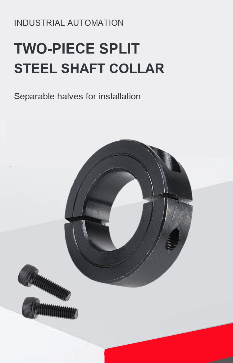
Two-piece collar overview
Two-piece split shaft collar.
Click the image to view full size.
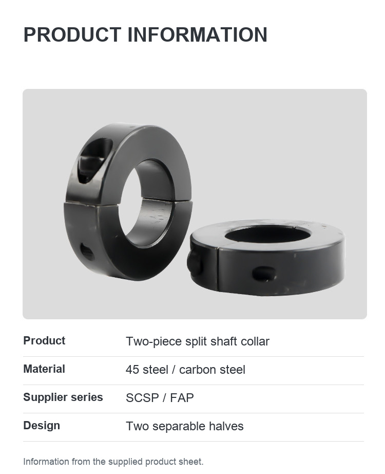
Two-piece product information
Product information from the supplied product sheet.
Click the image to view full size.
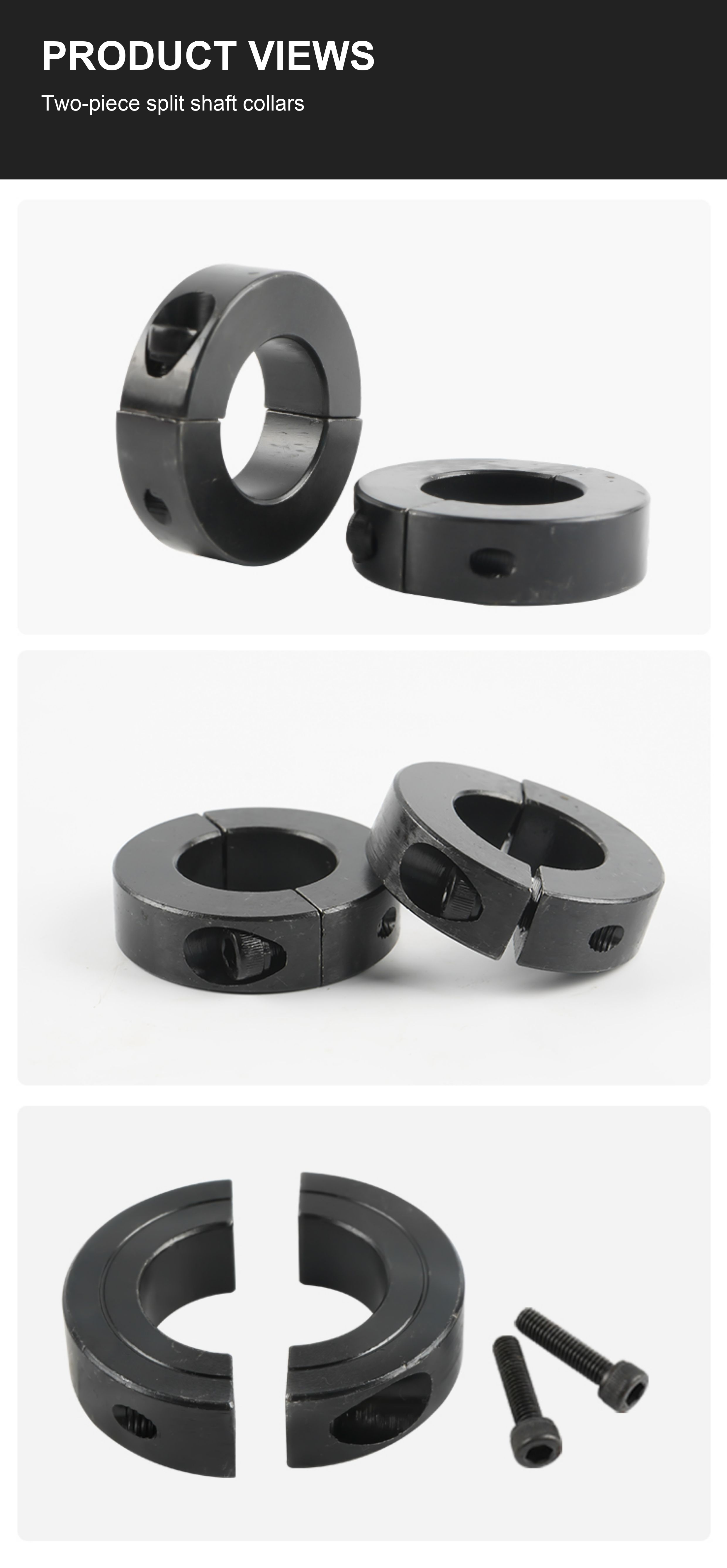
Product views
Two-piece split shaft collar photographs.
Click the image to view full size.
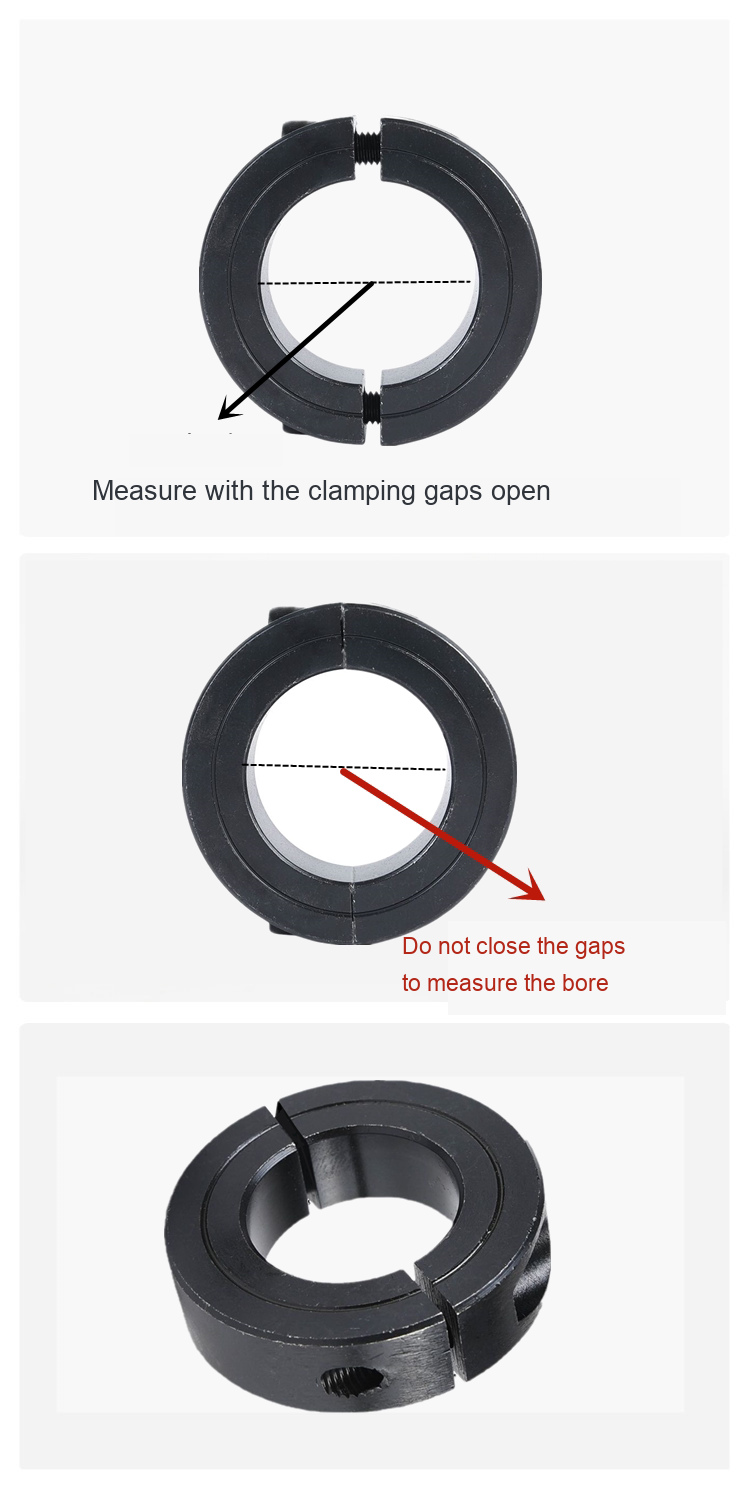
Two-piece installation and measurement
Measurement guidance for the two-piece design shown.
Click the image to view full size.
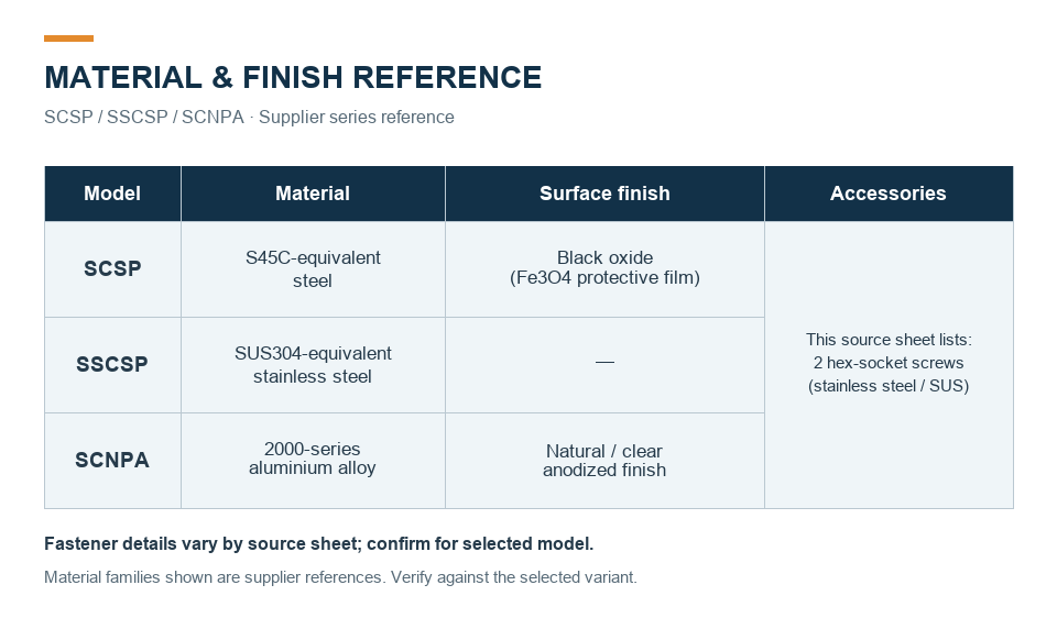
Supplier material series reference
Supplier series overview. Confirm material, finish and fastener details for the selected model.
Click the image to view full size.
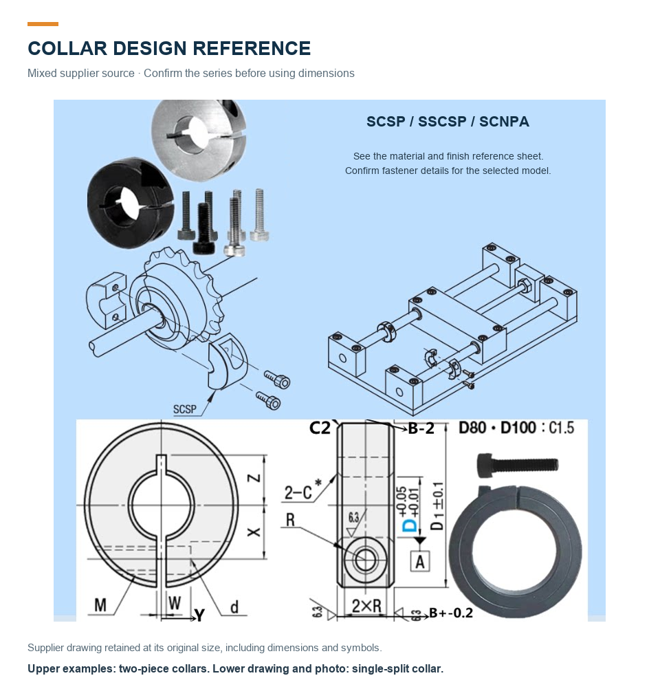
Collar design reference
Mixed supplier source: upper two-piece examples and lower single-split drawing. Match the reference to the selected model.
Click the image to view full size.
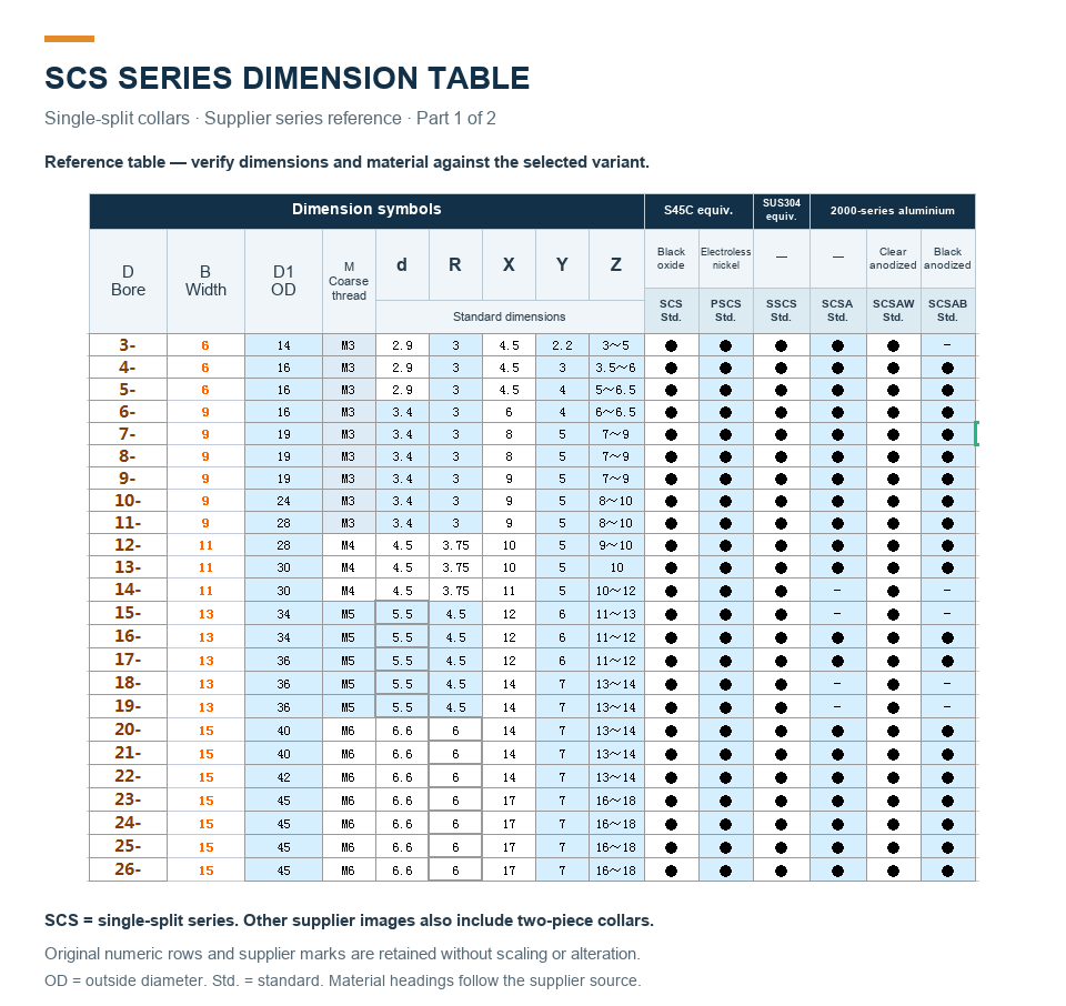
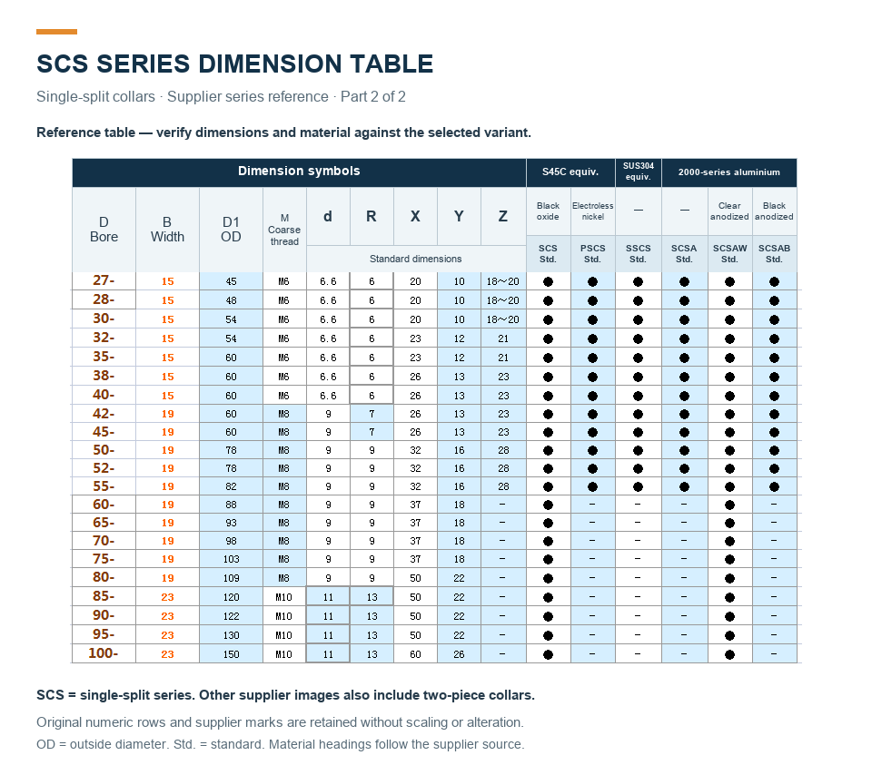
SCS single-split dimensions — part 1
SCS single-split supplier reference table. This is a different series from the SCSP drawing above. Verify values against the selected variant.
Click the image to view full size.
SCS single-split dimensions — part 2
Continuation of the SCS single-split reference table. Dots indicate source-series availability, not DEEGA stock.
Click the image to view full size.
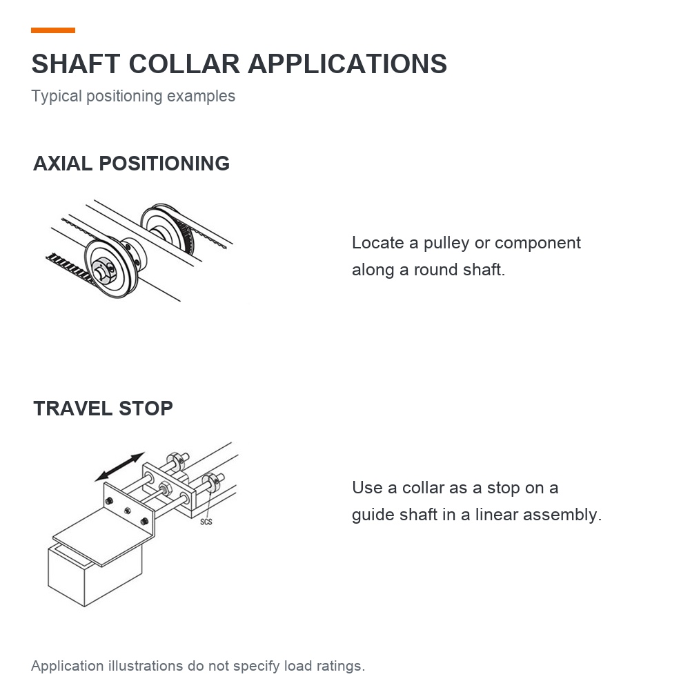
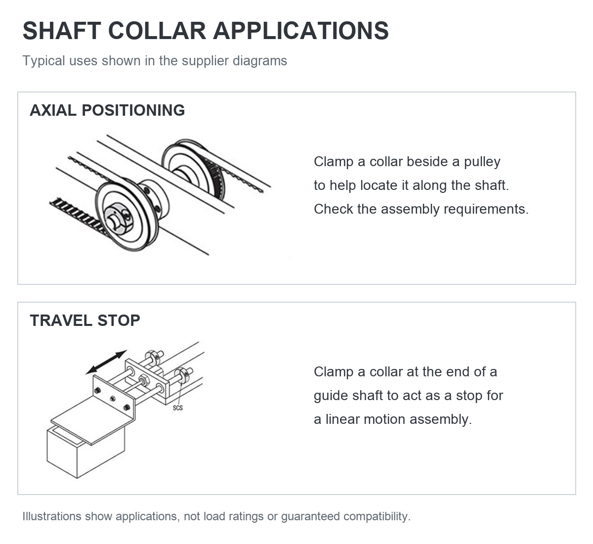
Shaft collar applications
Illustrations of axial positioning and travel-stop applications.
Click the image to view full size.
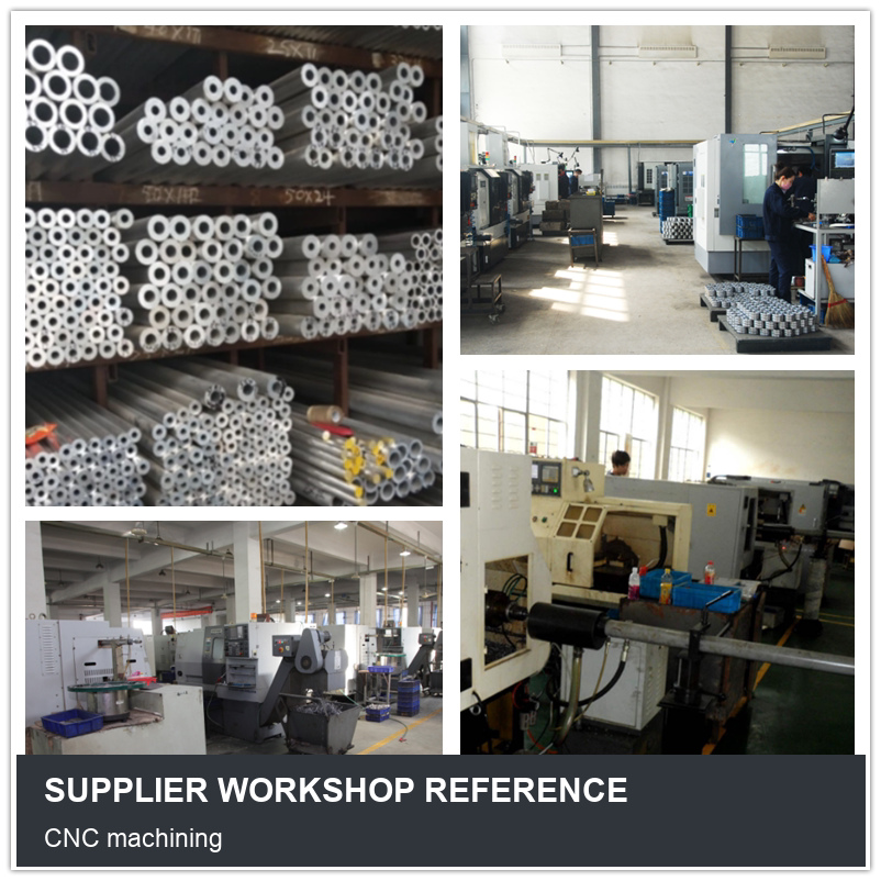
Supplier workshop reference
Workshop photograph provided in the source material.
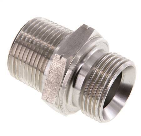
1 inch NPT x G 1 inch Stainless steel Double Nipple 40 Bar - Hydraulic. Check the thread standard, dimensions and material against your installation requirements before ordering.
Specifications
Model / SKU
FL2S-M-ST-100NG
Thread
1 inch
Thread (smaller)
1 inch
Connection type
Outer thread conical (NPT) (EV020241,EV020239)
Material
Stainless steel
Max pressure at 20 °C
40 bar
Fitting features
Hydraulic
Quality of material
Stainless steel 321 (1.4541)
Model
1-part
Length
55 mm
Shape
Straight
Wrench width
41 mm
Material connection 1
Stainless steel
Material connection 2
Stainless steel
Material quality connection 1
Stainless steel 321 (1.4541)
Material quality connection 2
Stainless steel 321 (1.4541)
Custom Requirements
Can’t find the size you need? Send us your drawing for a custom-made solution.
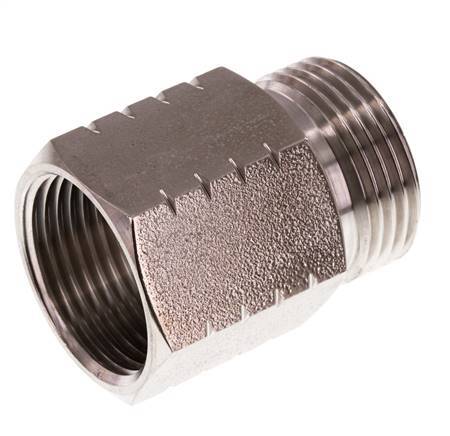
G 1 inch x 1 inch NPT M/F Stainless steel Reducing Ring 40 Bar - Hydraulic. Check the thread standard, dimensions and material against your installation requirements before ordering.
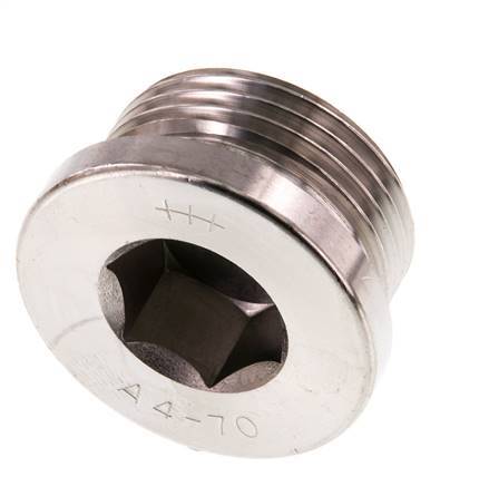
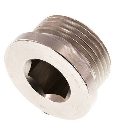
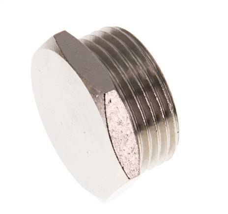
G 1 inch Stainless steel Closing plug with Inner Hex 40 Bar. Check the thread standard, dimensions and material against your installation requirements before ordering.
Specifications
Model / SKU
FL1-M-S-100G-I
Thread
1 inch
Connection type
Outer thread cylindrical BSP-G
Fitting features
Capped (TV000505)
Material
Stainless steel
Max pressure at 20 °C
40 bar
Material connection 1
Stainless steel
Material quality connection 1
Stainless steel 316 (1.4401)
Custom Requirements
Can’t find the size you need? Send us your drawing for a custom-made solution.
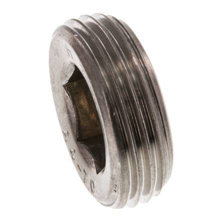
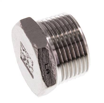
1 inch Stainless steel Closing plug with Inner Hex without collar 40 Bar. Check the thread standard, dimensions and material against your installation requirements before ordering.
Specifications
Model / SKU
FL1-M-S-100R-I-W
Thread
1 inch
Connection type
Outer thread conical BSP-R
Fitting features
Capped (TV000505)
Material
Stainless steel
Max pressure at 20 °C
40 bar
Material connection 1
Stainless steel
Material quality connection 1
Stainless steel 316 (1.4401)
Custom Requirements
Can’t find the size you need? Send us your drawing for a custom-made solution.
G 1 inch Nickel plated Brass Closing plug with Inner Hex 16 Bar. Check the thread standard, dimensions and material against your installation requirements before ordering.
Specifications
Model / SKU
FL1-M-BN-100G-I
Thread
1 inch
Connection type
Outer thread cylindrical BSP-G
Fitting features
Capped (TV000505)
Material
Brass
Max pressure at 20 °C
16 bar
Surface protection connection 1
Nickel-plated
Material connection 1
Brass
Custom Requirements
Can’t find the size you need? Send us your drawing for a custom-made solution.
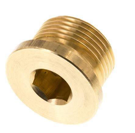
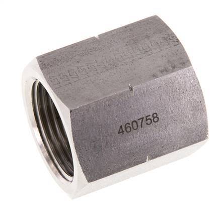
G 1 inch Brass Closing plug with Inner Hex 16 Bar. Check the thread standard, dimensions and material against your installation requirements before ordering.
Specifications
Model / SKU
FL1-M-B-100G-I
Thread
1 inch
Connection type
Outer thread cylindrical BSP-G
Fitting features
Capped (TV000505)
Material
Brass
Max pressure at 20 °C
16 bar
Material connection 1
Brass
Custom Requirements
Can’t find the size you need? Send us your drawing for a custom-made solution.
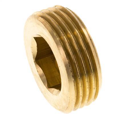
1 inch Brass Closing plug with Inner Hex without collar 16 Bar. Check the thread standard, dimensions and material against your installation requirements before ordering.
Specifications
Model / SKU
FL1-M-B-100R-I-W
Thread
1 inch
Connection type
Outer thread conical BSP-R
Fitting features
Capped (TV000505)
Material
Brass
Max pressure at 20 °C
16 bar
Material connection 1
Brass
Custom Requirements
Can’t find the size you need? Send us your drawing for a custom-made solution.
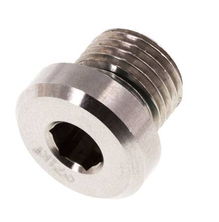
Plug M10 X 1 Stainless steel FKM with Internal Hex 400bar (5620.0psi). Check the thread standard, dimensions and material against your installation requirements before ordering.
Specifications
Model / SKU
F2EHD
Thread
M10 x 1
Connection type
Outer thread metric
Material
Stainless steel
Seal material
FKM (FPM)
Max pressure at 20 °C
400 bar
Min temperature
-20 °C
Max temperature
200 °C
Material connection 1
Stainless steel
Material quality connection 1
Stainless steel (1.4571)
Custom Requirements
Can’t find the size you need? Send us your drawing for a custom-made solution.
G 1 inch Nickel plated Brass Closing plug with Outer Hex 16 Bar. Check the thread standard, dimensions and material against your installation requirements before ordering.
Specifications
Model / SKU
FL1-M-BN-100G-E
Thread
1 inch
Connection type
Outer thread cylindrical BSP-G
Fitting features
Capped (TV000505)
Material
Brass
Max pressure at 20 °C
16 bar
Surface protection connection 1
Nickel-plated
Material connection 1
Brass
Custom Requirements
Can’t find the size you need? Send us your drawing for a custom-made solution.
1 inch NPT Male Stainless steel Closing plug with Outer Hex 16 Bar. Check the thread standard, dimensions and material against your installation requirements before ordering.
Specifications
Model / SKU
FL1-M-SH-100N-E
Thread
1 inch
Connection type
Outer thread conical (NPT)
Fitting features
Hydraulic (EV000448,TV000505)
Material
Stainless steel
Max pressure at 20 °C
16 bar
Material connection 1
Stainless steel
Material quality connection 1
Stainless steel 316 (1.4408)
Custom Requirements
Can’t find the size you need? Send us your drawing for a custom-made solution.
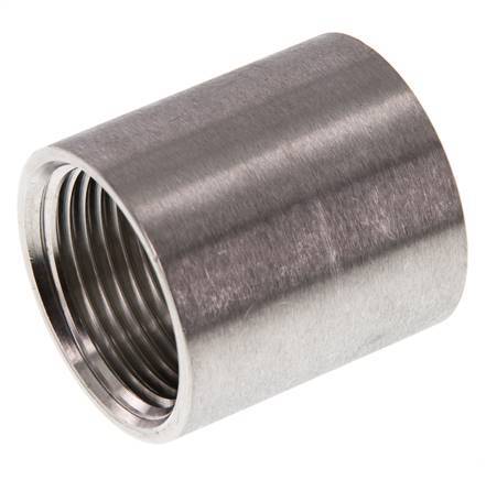
G 1 inch Stainless steel Socket 160 Bar - Hydraulic. Check the thread standard, dimensions and material against your installation requirements before ordering.
Specifications
Model / SKU
FL2S-F-ST-100G
Thread
1 inch
Thread (smaller)
1 inch
Connection type
Inner thread cylindrical BSP-G
Material
Stainless steel
Max pressure at 20 °C
160 bar
Fitting features
Hydraulic
Quality of material
Stainless steel (1.4571)
Model
1-part
Shape
Straight
Material connection 1
Stainless steel
Material connection 2
Stainless steel
Material quality connection 1
Stainless steel (1.4571)
Material quality connection 2
Stainless steel (1.4571)
Custom Requirements
Can’t find the size you need? Send us your drawing for a custom-made solution.
Rp 1 inch x 39.5mm Stainless steel Welding Socket 40 Bar DIN 2986 - 43mm. Check the thread standard, dimensions and material against your installation requirements before ordering.
Specifications
Model / SKU
FL2S-F-ST-100R-39P5-43L
Thread
1 inch
Thread (smaller)
1 inch
Connection type
Inner thread cylindrical BSP-Rp
Material
Stainless steel
Min pressure difference
0 bar
Min pressure
0 bar
Max pressure at 20 °C
40 bar
Standard
EN 10241 (DIN 2986) (TV000488)
Fitting features
Welding (TV000353)
Quality of material
Stainless steel (1.4571)
Model
1-part
Length
43 mm
Shape
Straight
Material connection 1
Stainless steel
Material connection 2
Stainless steel
Material quality connection 1
Stainless steel (1.4571)
Material quality connection 2
Stainless steel (1.4571)
Custom Requirements
Can’t find the size you need? Send us your drawing for a custom-made solution.
Rp 1 inch Stainless steel Round Socket 16 Bar. Check the thread standard, dimensions and material against your installation requirements before ordering.
Specifications
Model / SKU
FL2S-F-SH-100R
Thread
1 inch
Thread (smaller)
1 inch
Connection type
Inner thread cylindrical BSP-Rp
Material
Stainless steel
Min pressure difference
0 bar
Min pressure
0 bar
Max pressure at 20 °C
16 bar
Quality of material
Stainless steel 316 (1.4408)
Model
1-part
Shape
Straight
Material connection 1
Stainless steel
Material connection 2
Stainless steel
Material quality connection 1
Stainless steel 316 (1.4408)
Material quality connection 2
Stainless steel 316 (1.4408)
Custom Requirements
Can’t find the size you need? Send us your drawing for a custom-made solution.
Rp 1 inch x 39.5mm Stainless steel Welding Socket 40 Bar DIN 2986 - 20mm. Check the thread standard, dimensions and material against your installation requirements before ordering.
Specifications
Model / SKU
FL2S-F-ST-100R-39P5-20L
Thread
1 inch
Thread (smaller)
1 inch
Connection type
Inner thread cylindrical BSP-Rp
Material
Stainless steel
Min pressure difference
0 bar
Min pressure
0 bar
Max pressure at 20 °C
40 bar
Standard
EN 10241 (DIN 2986) (TV000488)
Fitting features
Welding (TV000353)
Quality of material
Stainless steel (1.4571)
Model
1-part
Length
20 mm
Shape
Straight
Material connection 1
Stainless steel
Material connection 2
Stainless steel
Material quality connection 1
Stainless steel (1.4571)
Material quality connection 2
Stainless steel (1.4571)
Custom Requirements
Can’t find the size you need? Send us your drawing for a custom-made solution.
1 inch NPT Stainless steel Socket 140 Bar - Hydraulic. Check the thread standard, dimensions and material against your installation requirements before ordering.
Specifications
Model / SKU
FL2S-F-S-100N
Thread
1 inch
Thread (smaller)
1 inch
Connection type
Inner thread conical (NPT)
Material
Stainless steel
Max pressure at 20 °C
140 bar
Fitting features
Hydraulic
Quality of material
Stainless steel 316 (1.4401)
Model
1-part
Shape
Straight
Material connection 1
Stainless steel
Material connection 2
Stainless steel
Material quality connection 1
Stainless steel 316 (1.4401)
Material quality connection 2
Stainless steel 316 (1.4401)
Custom Requirements
Can’t find the size you need? Send us your drawing for a custom-made solution.
1 inch NPT Stainless steel Round Socket 16 Bar. Check the thread standard, dimensions and material against your installation requirements before ordering.
Specifications
Model / SKU
FL2S-F-SH-100N
Thread
1 inch
Thread (smaller)
1 inch
Connection type
Inner thread conical (NPT)
Material
Stainless steel
Min pressure difference
0 bar
Min pressure
0 bar
Max pressure at 20 °C
16 bar
Quality of material
Stainless steel 316 (1.4408)
Model
1-part
Shape
Straight
Material connection 1
Stainless steel
Material connection 2
Stainless steel
Material quality connection 1
Stainless steel 316 (1.4408)
Material quality connection 2
Stainless steel 316 (1.4408)
Custom Requirements
Can’t find the size you need? Send us your drawing for a custom-made solution.
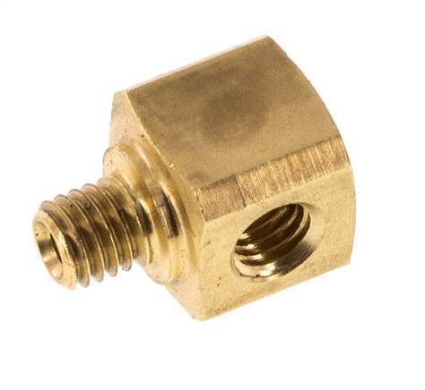
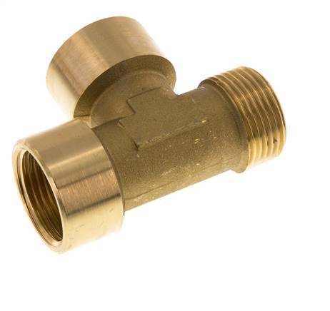
Tee Fitting M5 Male x Female Brass 16bar (224.8psi) [2 Pieces]. Check the thread standard, dimensions and material against your installation requirements before ordering.
Specifications
Model / SKU
F2FY3-X2
Thread
M5
Connection type
Outer thread metric (EV020240,EV020236)
Material
Brass
Max pressure at 20 °C
16 bar
Material connection 3
Brass
Material connection 1
Brass
Material connection 2
Brass
Custom Requirements
Can’t find the size you need? Send us your drawing for a custom-made solution.
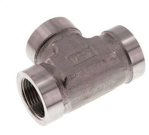
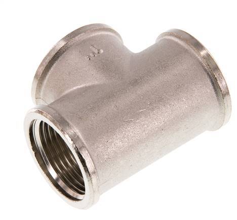
G 1 inch Stainless steel Tee 160 Bar - Hydraulic. Check the thread standard, dimensions and material against your installation requirements before ordering.
Specifications
Model / SKU
FL3T-F-S-100G
Thread
1 inch
Thread (smallest)
1 inch
Connection type
Inner thread cylindrical BSP-G
Material
Stainless steel
Fitting features
Hydraulic
Max pressure at 20 °C
160 bar
Model
T-piece
Material connection 3
Stainless steel
Material quality connection 3
Stainless steel 316 (1.4401)
Material connection 1
Stainless steel
Material connection 2
Stainless steel
Material quality connection 1
Stainless steel 316 (1.4401)
Material quality connection 2
Stainless steel 316 (1.4401)
Custom Requirements
Can’t find the size you need? Send us your drawing for a custom-made solution.
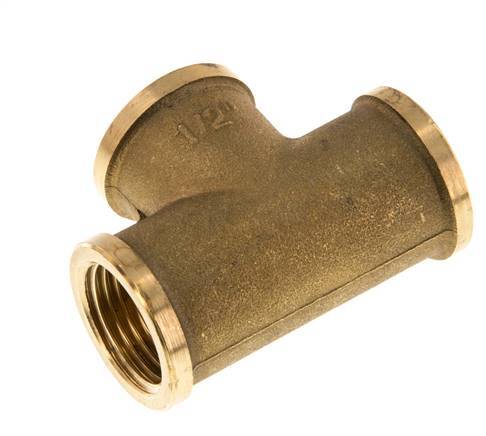
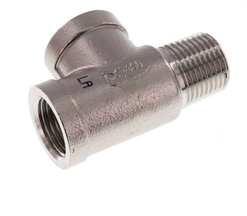
R 1/2 inch x Rp 1/2 inch M/F Stainless steel Tee 16 Bar. Check the thread standard, dimensions and material against your installation requirements before ordering.
Specifications
Model / SKU
FL3T-MF-SH-012R
Thread
1/2 inch
Thread (smallest)
1/2 inch
Connection type
Outer thread conical BSP-R
Material
Stainless steel
Max pressure at 20 °C
16 bar
Model
T-piece
Material connection 3
Stainless steel
Material quality connection 3
Stainless steel 316 (1.4408)
Material connection 1
Stainless steel
Material connection 2
Stainless steel
Material quality connection 1
Stainless steel 316 (1.4408)
Material quality connection 2
Stainless steel 316 (1.4408)
Custom Requirements
Can’t find the size you need? Send us your drawing for a custom-made solution.
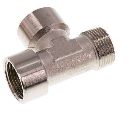
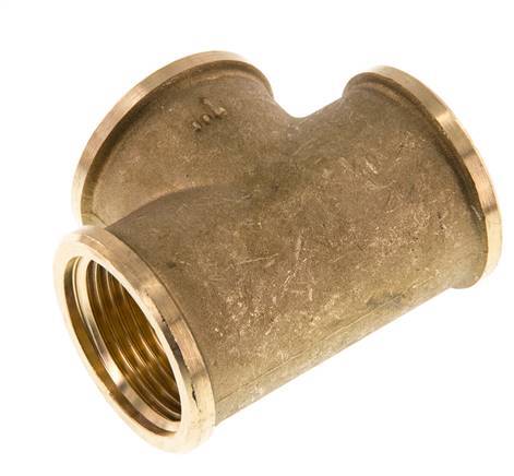
R 1 inch x G 1 inch M/F Nickel plated Brass Tee 16 Bar. Check the thread standard, dimensions and material against your installation requirements before ordering.
Specifications
Model / SKU
FL3T-MF-BN-100RG
Thread
1 inch
Thread (smallest)
1 inch
Connection type
Outer thread conical BSP-R
Material
Brass
Max pressure at 20 °C
16 bar
Model
T-piece
Surface protection connection 1
Nickel-plated
Surface protection connection 2
Nickel-plated
Material connection 3
Brass
Surface protection connection 3
Nickel-plated
Material connection 1
Brass
Material connection 2
Brass
Custom Requirements
Can’t find the size you need? Send us your drawing for a custom-made solution.
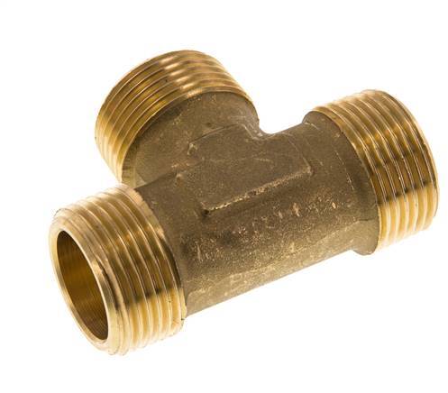
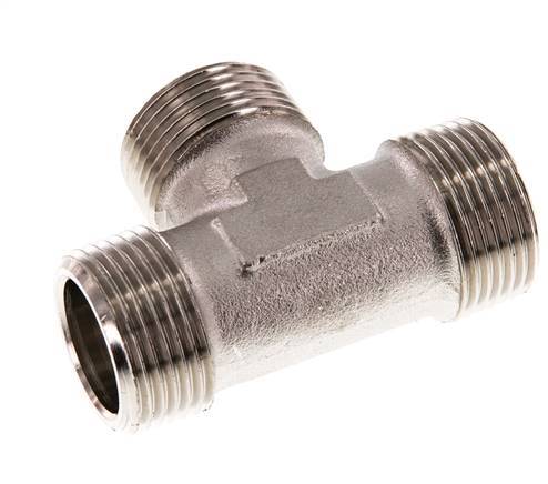
R 1 inch Male Nickel plated Brass Tee 16 Bar. Check the thread standard, dimensions and material against your installation requirements before ordering.
Specifications
Model / SKU
FL3T-M-BN-100R
Thread
1 inch
Thread (smallest)
1 inch
Connection type
Outer thread conical BSP-R
Material
Brass
Max pressure at 20 °C
16 bar
Model
T-piece
Surface protection connection 1
Nickel-plated
Surface protection connection 2
Nickel-plated
Material connection 3
Brass
Surface protection connection 3
Nickel-plated
Material connection 1
Brass
Material connection 2
Brass
Custom Requirements
Can’t find the size you need? Send us your drawing for a custom-made solution.
Tee Fitting 1 inch NPT Female Stainless steel High Pressure 140bar (1967.0psi). Check the thread standard, dimensions and material against your installation requirements before ordering.
Specifications
Model / SKU
F2G27
Thread
1 inch
Connection type
Inner thread conical (NPT)
Material
Stainless steel
Fitting features
High pressure (TV000234)
Max pressure at 20 °C
140 bar
Model
T-piece
Material connection 3
Stainless steel
Material quality connection 3
Stainless steel (1.4571)
Material connection 1
Stainless steel
Material connection 2
Stainless steel
Material quality connection 1
Stainless steel (1.4571)
Material quality connection 2
Stainless steel (1.4571)
Custom Requirements
Can’t find the size you need? Send us your drawing for a custom-made solution.
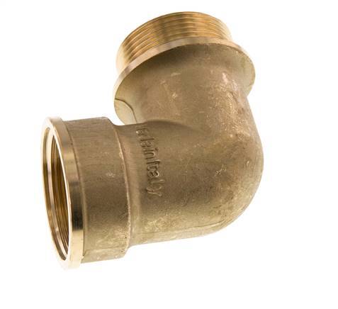
G 1 1/2 inch F/M Brass 90 deg Elbow Fitting 16 Bar. Check the thread standard, dimensions and material against your installation requirements before ordering.
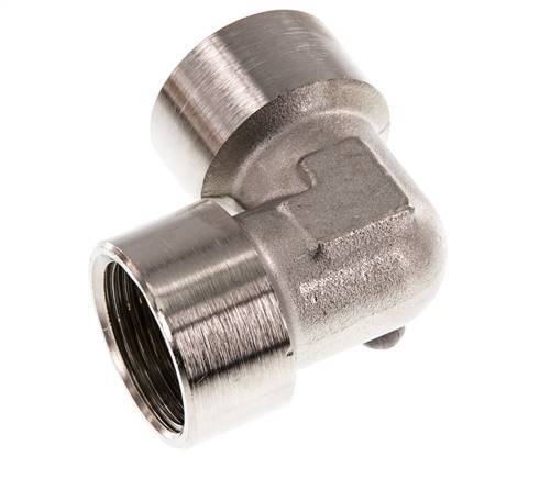
G 1 inch Nickel plated Brass 90 deg Elbow Fitting 16 Bar. Check the thread standard, dimensions and material against your installation requirements before ordering.
Specifications
Model / SKU
FL2E-F-BN-100G
Thread
1 inch
Thread (smaller)
1 inch
Connection type
Inner thread cylindrical BSP-G
Material
Brass
Max pressure at 20 °C
16 bar
Model
1-part
Shape
Elbow
Bend angle
90 °
Surface protection connection 1
Nickel-plated
Surface protection connection 2
Nickel-plated
Material connection 1
Brass
Material connection 2
Brass
Custom Requirements
Can’t find the size you need? Send us your drawing for a custom-made solution.
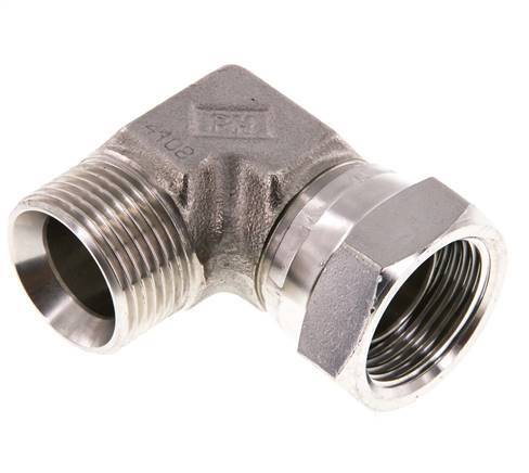
G 1 inch M/F Stainless steel 90 deg Elbow Fitting 150 Bar - Hydraulic. Check the thread standard, dimensions and material against your installation requirements before ordering.